DIY RS-232 Interface for Commodore C64 for under $15

If you have a Commodore 64, chances are you’ll eventually need to connect a modem or other serial device to it. You’ll find that’s not quite that easy since the C64 doesn’t have a standard RS-232 serial port. What it does have is called the “user port” and it can do serial over this port but it needs to be changed from TTL levels (0 to +5v) to RS-232 levels (-15v to +15v).

If you’ve ever attempted to purchase a VIC-1011a terminal type, SwiftLink or Turbo232 from eBay you’ll quickly find out that the price gets out of hand. Expect to pay upwards of $100 or more for these adapters.

Luckily, there’s an inexpensive way to get a RS-232 port on your C64 and it’ll cost you less than $15. Ready?

You’ll need these parts for the project.

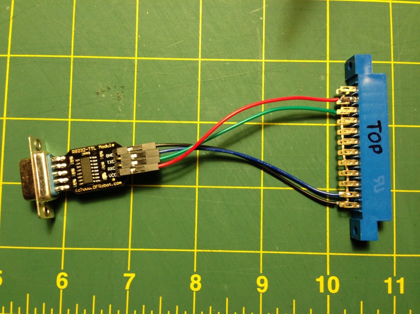
Connect the RS232-TTL module directly to the C64 user port edge connector using the table below.

RS232-TTL Module C64 User Port
GND A & N
TXD M
RXD B & C
VCC 2

Update! Alwyz from 1200baud suggested that connecting VCC isn’t necessary and potentially dangerous. I’ve had zero problems with mine as listed here. I’m providing this warning so you can make your own decision!

C64 RS-232 Adapter

Observe which side of the user port connector is the top (it’s the one with numbers– letters are on the bottom). It’s helpful to write on it with marker. For wire I used female jumper wire that I cut one end off. For GND and RXD you’ll need to jumper two of the pins together on the user port connector. I used a small bit of CAT5 solid core wire.

Once you’ve got it connected, add the null modem adapter and connect your modem. You may need to also use a gender changer and/or a 9 pin to 25 pin adapter depending on your modem.

Fire up CCGMS, Novaterm or Striketerm, set the baud rate to 2400, set the port to the user port and give it a few “AT” commands. You should see “OK” being returned. If it doesn’t, make sure you have a null modem adapter (test it on another machine to confirm) and double check your connections.

As with any tutorial you find online, be responsible and double check my work and your work before proceeding.

How to get software to disk for your Commodore 64

Commodore 64It’s a question that pops up from time to time on forums from Lemon64 to Reddit C64.
“Yes! I just got a Commodore 64!! Now how do I get disk images onto disk so I can do something?”

It’s not straight forward. Folks in the Apple II world have a fantastic program called ADTPro that can work over a simple audio cable connected to your laptop headphone and microphone jack (or serial). Doesn’t get any easier than that.

On the Commodore, disc images are stored in .D64 format which is an image of a standard 1541 floppy. Most software you find is available this way. You may also find .D71 and .D81 which are for 1571 and 1581 formats but these are less common. A great place to find C64 software is the CBM8BIT.com Search. Once you have your disk images, you’re ready to make some floppies. Below are some of the options to “burn” disk images for your Commodore 64.


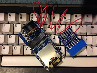
uIEC/SD2IECuIEC/SD2IEC ($50-60) is probably the easiest overall solution. With this small device, you can load .D64 images from your Mac or PC onto a SD card. Inserting into the uIEC, it will show up to the C64 as an extremely large volume. But merely having a .D64 image doesn’t get you very far– you need to “burn” the image to a real floppy. Fortunately, there’s D64it which can do just that. It’s a little slow as the author admits, but it gets the job done. Things are sped up considerably if you have the JiffyDOS ROM ($20) installed in your C64 since the uIEC is JD compatible. Don’t forget a 6-pin IEC cable!


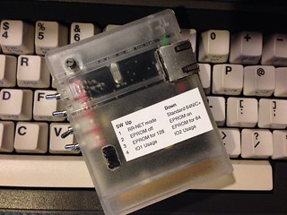
64NIC+64NIC+ ($50-59) adds Ethernet capability to your Commodore 64 as well as a ROM socket that can accommodate up to 256kB ROMs. With networking capability, now you’re able to use WarpCopy64 which can upload and download entire disc images to your PC. There’s a bit of a chicken and egg problem here since you’re going to need WarpCopy64 on disk first before you can create new disks.


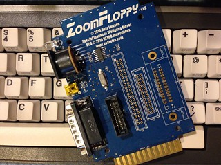
ZoomFloppyZoomFloppy ($35) is a great solution to connect your Commodore 1541 to your Mac or PC via USB. ZoomFloppy is a modern version of the “X” series cables which required an old PC with a parallel port plus knowledge of IRQ and ports (see below). After installing OpenCBM software on your Mac or PC, you can read and write D64 images quickly and easily– no fuss. Hands down, this is my preferred way to read and write floppies.


If you’re lucky to have a terminal program already on floppy on your C64, you can do the serial route. Of course, you’ll also need an adapter that plugs into the C64 user port to give you standard RS-232 signals. These can be difficult to come by if you don’t have one, like the Commodore made VIC-1011a. One could also build this USB to RS-232 interface for your C64 for $15.


If you have a PC that’s old enough to have a parallel port on the motherboard, you might have good luck with “X” series parallel cables. These cables connect your parallel port to the IEC port of a 1541. From there, you can run Star Commander in DOS mode to read and write files and images. I started using this method years ago but abandoned it for the ZoomFloppy.

So there you have it. There’s no shortage of solutions and every solution is most likely going to cost you something. But each is a great investment and keeps the scene going with folks creating new methods. This list isn’t exhaustive– if you know of one or have experience with any of these, leave a comment!

Reddit r/retrobattlestations Commodore 64 Port


For the next two weeks, it’s BASIC Week 2 at Reddit r/retrobattlestations. You can participate with your Commodore 64 or at least play along with your favorite emulator. I’ve ported the code to the C64 and you can get the code from the thread on Reddit. Or you can download the D64 image here to make your own disk or to use with an emulator like VICE.

Have fun!

The PP&S Frame Grabber 256 for Amiga

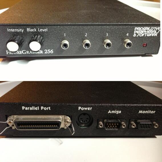
The Frame Grabber 256 by Progressive Peripherals and Software (PP&S) is a video frame digitizer capable of capturing a single frame from moving video in up to 256 shades of gray. There was also a color version simply called Frame Grabber. I owned the color version in the late 80’s/early 90’s but eventually sold it to fund other things.

A few years ago, I won an eBay auction that was a Commodore grab bag. Among the items was the Frame Grabber 256 hardware box but nothing else. It was missing the manual, the software and the power supply. My search for these items came up cold and I shelved it.

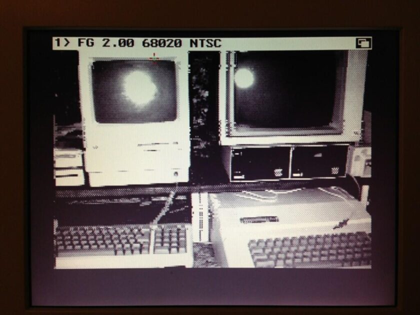
The unit is very interesting since it can drive an Amiga monitor natively and display the NTSC video through it, without the aid of the computer to process it.


Recently, my interest was renewed so I began looking again and I struck gold. I’ll share the wealth with you below.

It’s important to note the power supply and the pin-out that’s printed on top of it uses a numbering scheme in the diagram that is very wrong.

The pin numbers/layout are wrong. The position and values are correct. The locations and their corresponding values are correct though. When you go searching for a suitable power supply, you’ll need to use the following.

  • Pin 1: COM
  • Pin 2: GND
  • Pin 3: +5v
  • Pin 4: -12V
  • Pin 5: +12V

The correct pin layout:

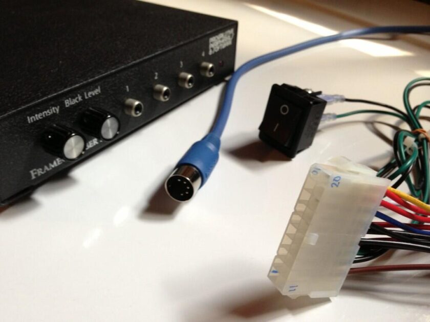
Instead of purchasing a new power supply, I created an adapter cable for an ATX power supply. I used the table below for the connections.

  • DIN Pin 1 to ATX Pin 13
  • DIN Pin 2 to ATX Pin 3
  • DIN Pin 3 to ATX Pin 4
  • DIN Pin 4 to ATX Pin 12
  • DIN Pin 5 to ATX Pin 10

You can get a 3 pack of 3ft MIDI cables for the DIN portion for $1.97 at Radio Shack. They will price match in the store. It’s an unusual bargain. Unlike most MIDI cables, these have all five pins connected.

It goes without saying, I’m not responsible for any damage that may succumb to your gear. Double check everything with a second source!

Moment of truth came and I connected it to my Amiga 4000 via a parallel cable, and connected a small point and shoot digital camera that has an NTSC video out cable. Success! There’s some tearing in the image along the way that might be caused by a bad video cable but otherwise it looks like it’s working.

Make an Apple // disc for BASIC week at Reddit RetroBattlestations

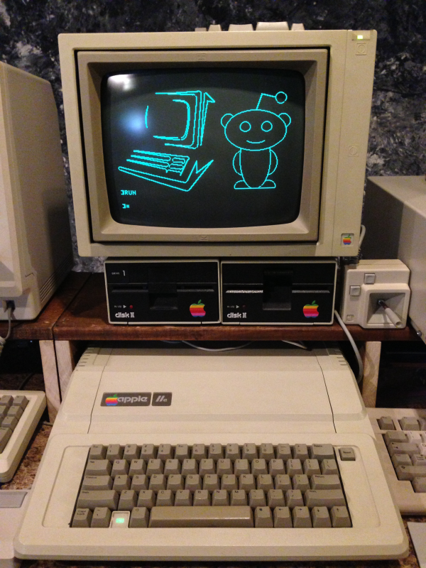
Apple //e for BASIC weekBASIC week at Reddit /r/retrobattlestations is over but you can relive the fun on your Apple // without any typing! Simply follow these steps to download the disk image to a new disk for your machine.

  1. Connect your laptop, tablet or phone’s headphone jack to the tape input jack on the back of your Apple // using a 1/8″ mini headphone cable.
  2. Turn the volume up to maximum.
  3. Turn on your machine and hold control and hit reset to get to a ] prompt.
  4. Insert a blank disk into drive 1 (it will be erased!).
  5. Turn on caps lock and type LOAD and hit return.
  6. Begin playing the .WAV file below on your device.

If all goes well, in about 2 minutes you should have a floppy that you can now boot from. When it’s finished, hit return to reboot your machine. ProDOS should load BASIC. Once it does, type LOAD REDDIT and then RUN.

[Apple // .WAV file to disc for BASIC week program 5.5MB]

Credit for creating the .WAV file from a .DSK image goes to C2T found at ASCII Express.

Enjoy!


Create a local web-based Apple II disc server

Here are the steps I used to create a local web-based Apple II disc server. This method uses the c2t tool for converting .dsk disk images to .wav audio files suitable for playback into the tape in jack of the Apple II. The Apple Disc Server site does this with preexisting disk images already converted to .wav files. I thought it would be nice to create a web-based service that would allow you to convert .dsk images to .wav files on the fly. This enables you to browse Apple II software with your iPad and instantly convert it to a disk.


  • Enable Apache server on your Mac
  • Create a directory (default is “c2t”) for the new service in /Library/WebServer/Documents
  • Create a new temporary directory (default is “tmp”) inside this new directory
  • Change ownership and permissions
     sudo chown www:www /Library/WebServer/Documents/c2t/tmp
     sudo chmod g+w /Library/WebServer/Documents/c2t/tmp
  • Download c2t and wget and install in your path

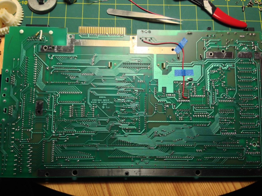
Adding S-Video to an Atari 800XL

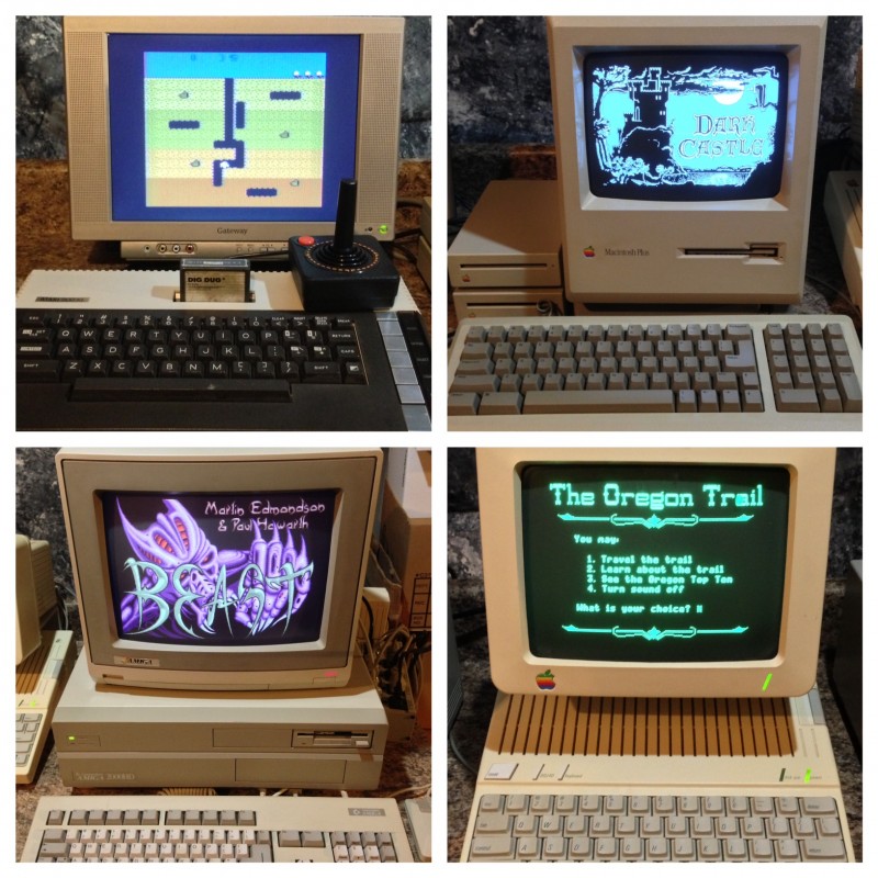
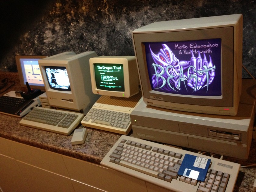
Recently I setup a few of the computers from my retro computing collection. Along with the Amiga 2000, Apple IIc, and Macintosh Plus was the Atari 800XL.


I’ve not used it all that much and thought it deserved a little hands on time. When I acquired it I also purchased a 5 pin DIN plug for the video jack on the rear to bring out stereo RCA audio (although it’s just mono) and s-video. I was puzzled when I plugged it in and turned it on to find that the video was only in black and white. I switched to the RF modulator and saw color so I knew the computer was working fine. I searched and discovered that some (maybe all?) Atari 800XL’s have provisions for s-video, namely separated luma (brightness) and chroma (color) but Atari neglected to connect the chroma to the plug. This explains why the image has no color.


I searched and was surprised that I didn’t find all that much information on the subject. One site called the seemed to have the most information but I found the directions confusing and images that were hard to see. I kept searching and found a clear forum posting on AtariAge (post #8), also summarized below.

  1. REMOVE C56 capacitor (if present)
  2. Lift C54 right-hand side, preferably by inserting an on-off switch (if you want to preserve composite out).
  3. On the underside of the motherboard, solder chroma-signal wire from R67/R68 junction, to chroma pin in video DIN port pin 5. Follow the cable pathway exactly as shown so the RF shielding fits back on.
  4. Adjust brightness/contrast/saturation on your monitor. Don’t underestimate this step as I did at first. It’s important and made all the difference in the quality of the final picture.


With those small changes, I now have crisp s-video output from my Atari 800XL to an LCD monitor. The picture looks fantastic!

DIY C64 Diagnostic and Dead Test Carts

If you’ve ever attempted to repair a dead Commodore 64 beadbin, you know how frustrating it can be. You’re lucky if the machine turns on and shows something on the screen. This at least gives you some clues as to the problem. However, more often and not, you’re stuck with a blank screen. It doesn’t tell you much other than just about any chip in the computer is bad, or even a bad power supply. After checking the obvious things like missing chips, reseating socketed chips and checking the power supply voltages, the next place to go would be one of the two diagnostic carts that were available from Commodore service technicians.

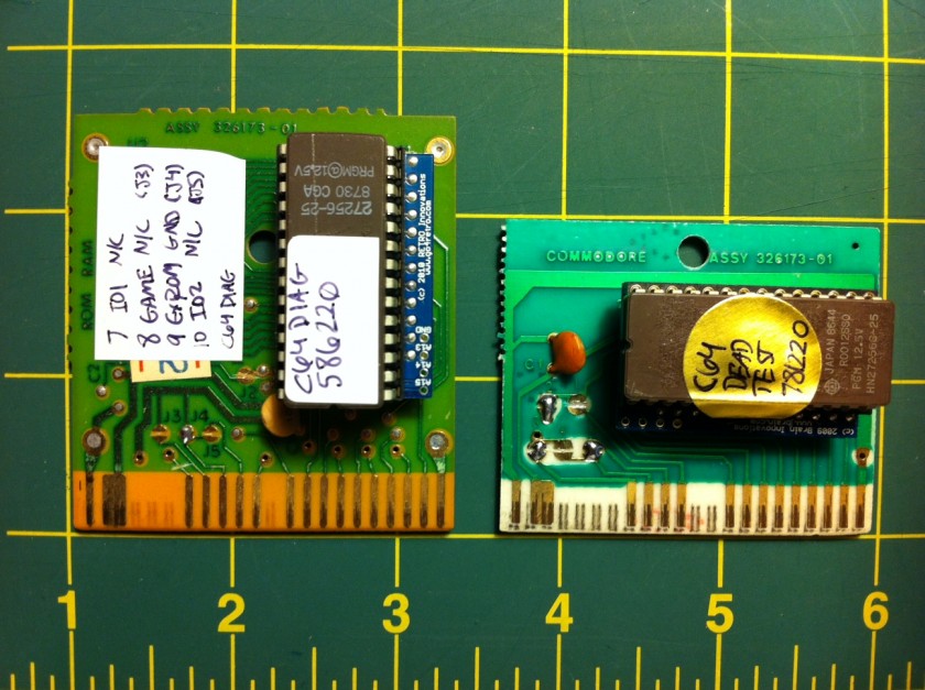
The two test carts that were available are the C64 Diagnostic cart and the C64 Dead Test cart. Together, these carts are very useful in identifying problems. In order to use them, you need them in a cartridge. The diagnostic cart also had a cable harness that would test certain ports– it’s not required but will report false problems if not present. If you’ve followed my posts, you’ll know that I have a tutorial on how to convert an existing cartridge into a EPROM carrier board. In this case, instead of creating a 24 to 28 pin adapter, I’ve purchased the Retro Innovations 2364 Adapter for $5. It’s well worth the price.


In both cases, I’ve used a Commodore cartridge with ASSY # 326173-01. The thing you’ll find odd about the picture is the carts look completely different but have the same ASSY number. The good news is they behave the same way.

There are solder jumpers on the cart labeled J1 through J5. These control certain lines on the cartridge port that tell the C64 what type of peripheral is connected. Below is a table of the settings for the two carts.

C64 Diagnostic Cart Jumpers
J1: Closed (ROMH)
J2: Open (ROML)
J3: Open (GAME)
J4: Closed (EXROM)
J5: Open (I/O 2)

C64 Dead Test Cart Jumpers (Ultimax Mode)
J1: Open (ROMH)
J2: Closed (ROML)
J3: Closed (GAME)
J4: Open (EXROM)
J5: Closed (I/O 2)

Raspberry Pi And A Personal Weather Station

Ambient Weather WS-1090 and Raspberry PiI’ve had the Ambient Weather WS-1090 personal weather station for about a year and it’s worked well. It has a base station receiver that wirelessly receives the data from the sensors outside. The unit stores about 5 days worth of data but goes no further. It would be nice to be able to archive this data and also have real time data accessible from outside the home. It has a USB port and includes software but I’m not keen on keeping a PC on 24/7 just for that mundane task.

Enter the Raspberry Pi, a $35 credit-card sized computer that runs a variant of Debian Linux with HDMI, USB and Ethernet ports built in. A quick search revealed that Peter Mount has done all of the hard work already in a part 1 and part 2 tutorial. The tutorials are excellent, well written and unlike most Linux projects I try, there were no errors. I used a 4GB SD card that I had laying around and began with the Raspbian “wheezy” image from 2012-08-16. I expanded the partition to fill the card and enabled SSH so I could do the work from another machine.

I’m now pushing data every 5 minutes to Weather Underground were it automatically builds historical graphs of the weather from the PWS. I still need to get a proper solar radiation shield for the temperature sensor as it tends to read much warmer on sunny days.