The Macintosh Portable was Apple’s first foray into mobile computing. This early laptop, err, luggable, weighed in at 16 lbs due to the 6V sealed lead-acid battery and desktop floppy and hard drives. But because of this, the Snow White designed case is roomy inside and a prime candidate for a overhaul.
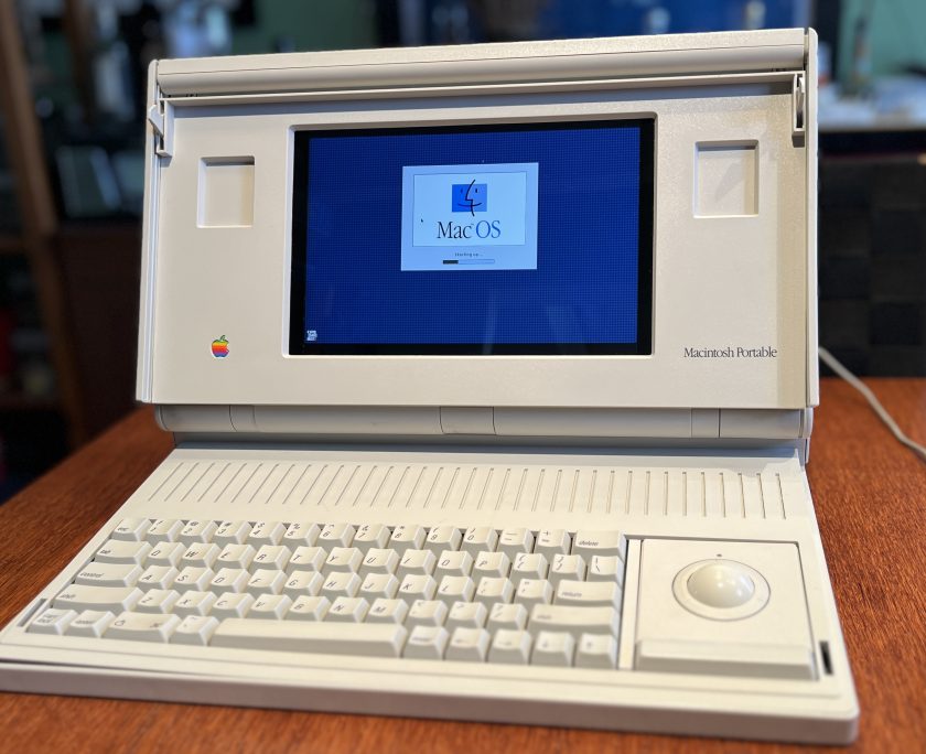
My particular Macintosh Portable M5120 is the non-backlit version. It came with one floppy and a hard drive and retailed for $7,300 in 1989. I’ve tried over the course of several years to get this machine working. I’ve replaced the leaky capacitors on the motherboard, cleaned it in an ultrasonic bath several times, and tried two different hybrid modules but nothing was able to get this machine running again.
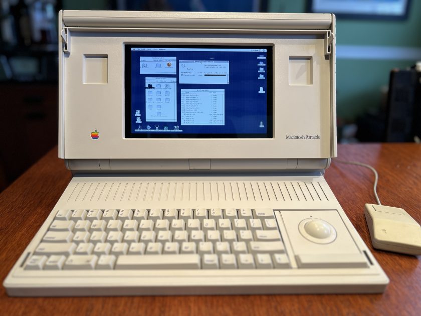
My goal is to give this beautiful machine a new lease on life while at the same time keeping the appearance the same and not making any permanent modifications to the case. I want it to look and work as close to the original Macintosh Portable (including the floppy drive!) while also having the capability of running a modern OS. The internal components have been removed and stored properly in the event there’s a new method for repair in the future.
Let’s get to the build!
Raspberry Pi
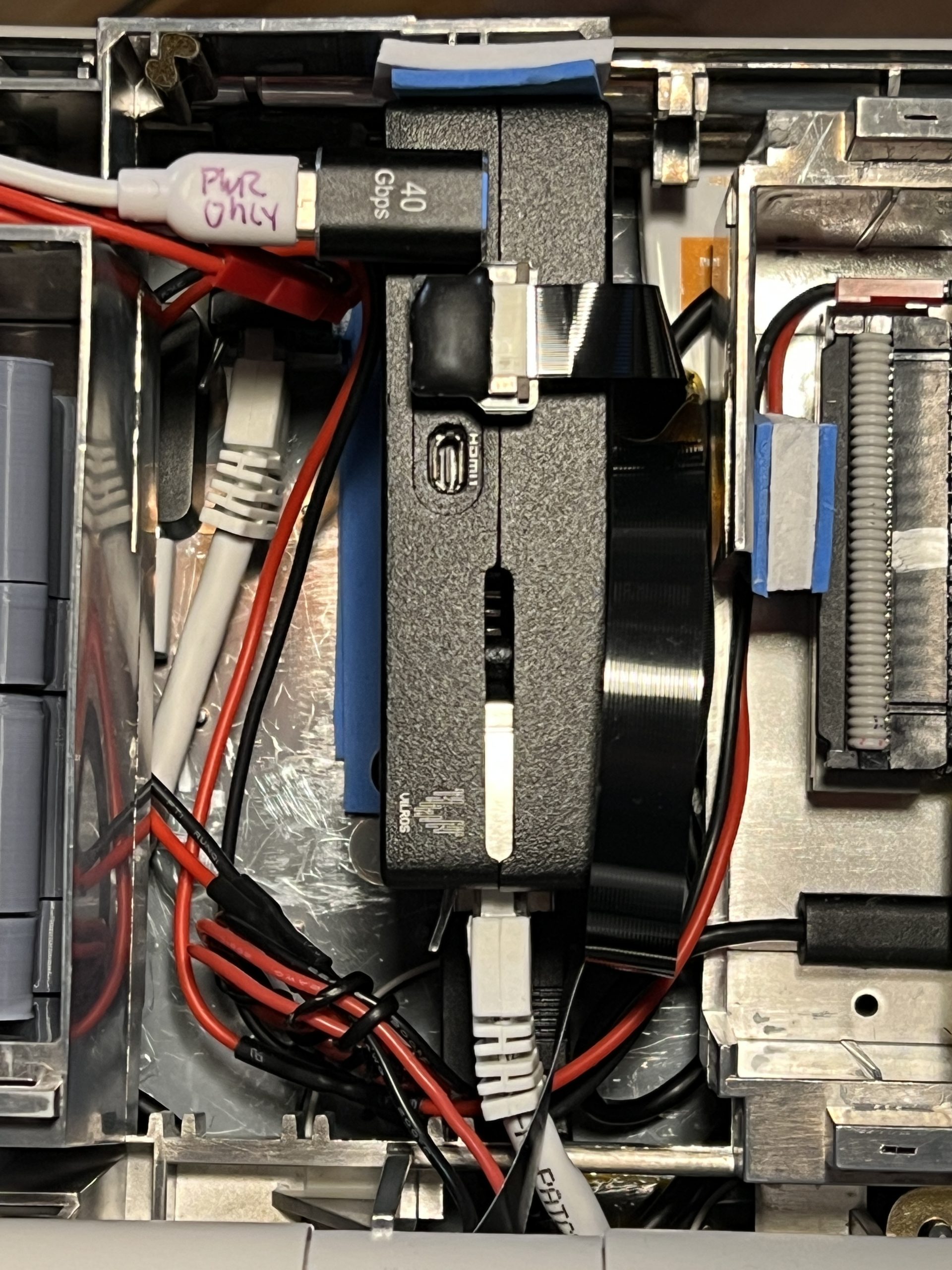
The obvious choice for the computer was a Rasbperry Pi. Here, I’ve opted for a Pi 5 with 8GB of memory. It’s housed in the rear of the Portable on its side where the modem and memory cards were. I’m using a Vilros metal case here which includes an integrated fan. Power is fed in via a right-angled USB-C connector (a great way to use those annoying power-only USB cables!)
Why not a Raspberry Pi 4? Well, to be honest, once I tried using a Raspberry Pi 5 and saw the incredible speed increase and performance over the Pi 4, I was sold and couldn’t go back. Plus, the anticipated power draw savings just wasn’t enough to justify using a slower machine.
LCD Display
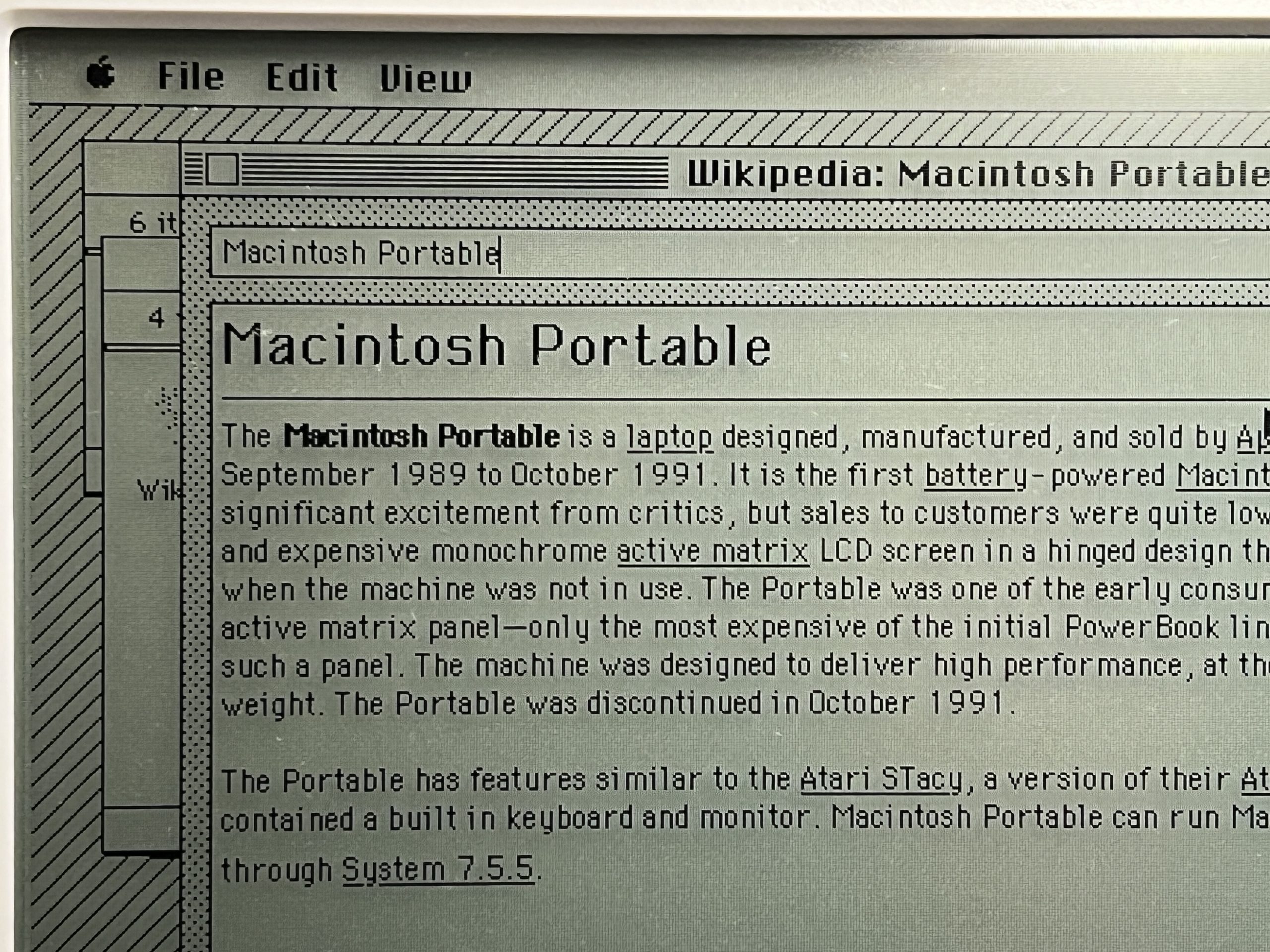
The LCD display in the original Macintosh Portable was a relatively fast and very sharp monochrome active matrix LCD display which, at the time, was very expensive. I intended to use the LCD display and use a PixelWrangler which can show HDMI on arbitrary displays. But I’m not certain the original display even works, as they are prone to row and column failures. I may revisit this.
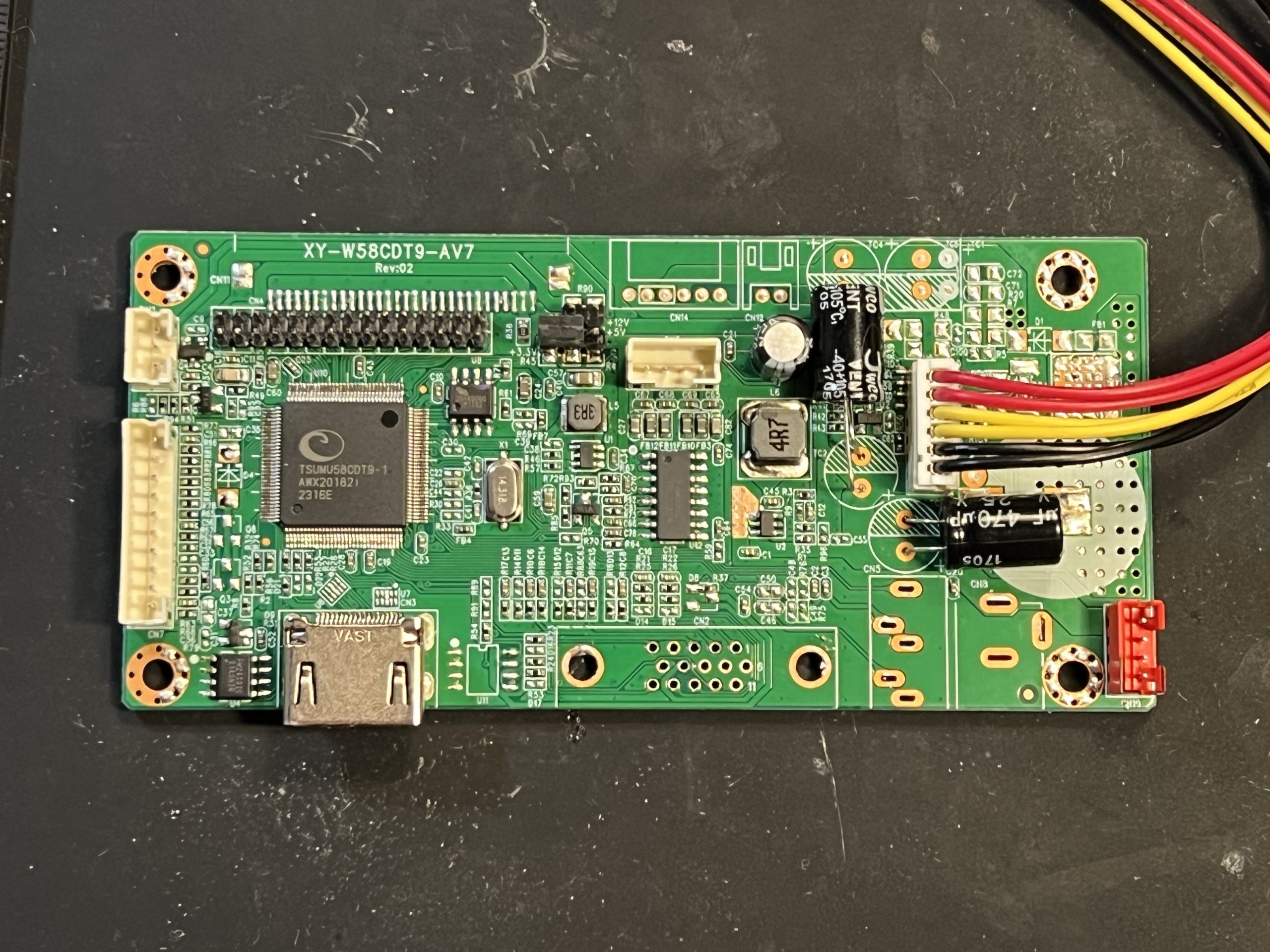
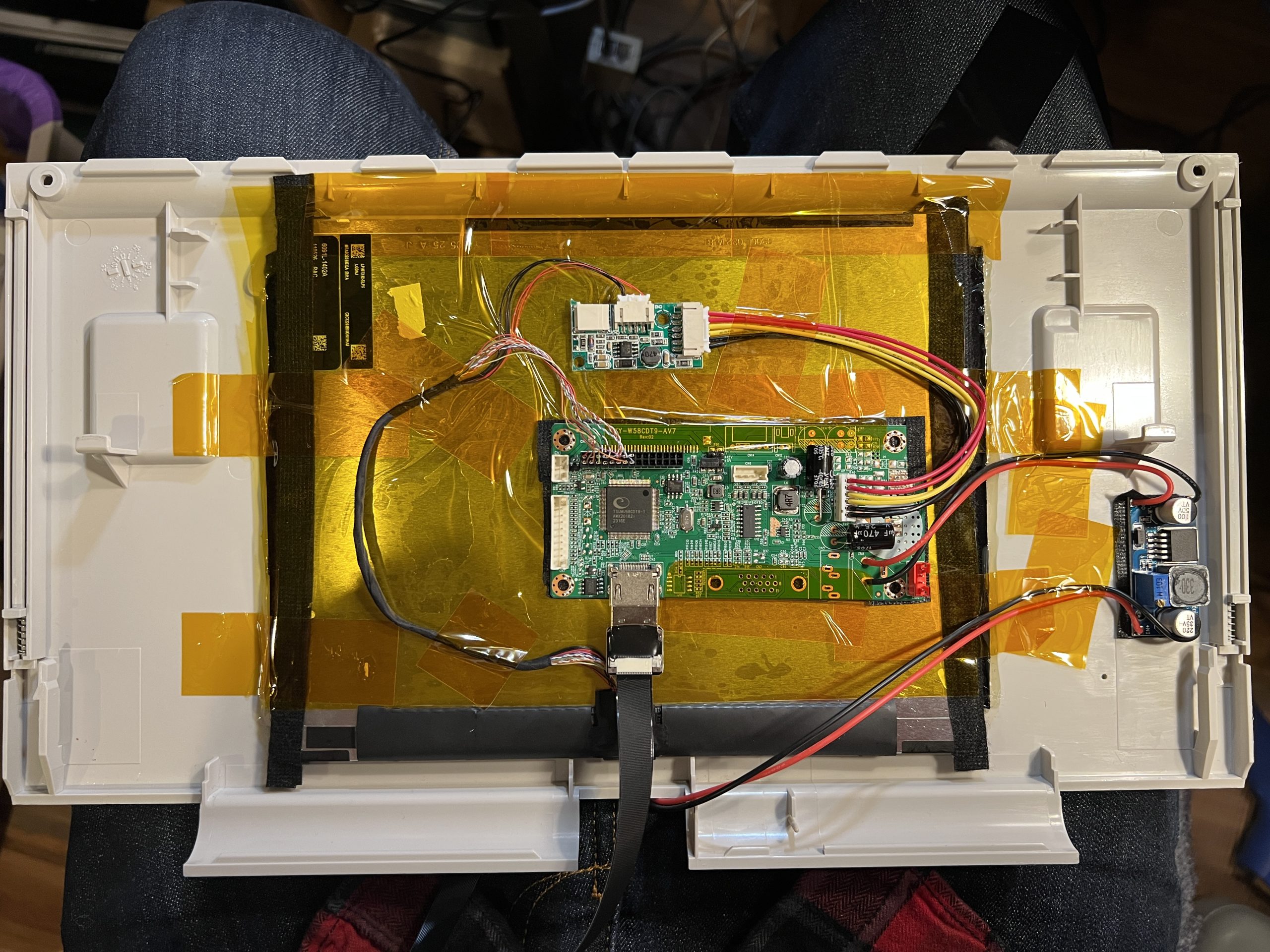
Instead, I went with a LCD module that I pulled from a broken iPad 2 and used a simple HDMI/VGA driver board to power it. Getting this all to fit inside the screen housing was a bit of a challenge. I used hot glue and Kapton tape so my mods were reversible. A 1.5mm thin sheet of 8×10 acrylic was cut to size to serve as the front of the display. The display driver board was a bit too tall so I removed the tall components that I didn’t need like the VGA, power, and sound ports as well as changed the through hole caps to be on the side. I used a boost converter to power the driver board that takes in 5V and provides 12V out.
The display isn’t a perfect fit due to the uncommon resolution of the original display (640×400). It’s a bit too tall and a bit too narrow. To resolve this, I used black vinyl to mask the left and right of the acrylic. On the top and bottom, well, the display just continues on beyond the bezel. I use software to limit the display vertically. The result is a display that’s slightly inset from the bezel and hardly noticeable. The Portable’s original resolution of 640×400 scales perfectly to 1024×640 and fits nicely within the opening.
The LCD display is actually upside down. This was to accommodate the short LCD display connector. Boot messages scroll by upside down but things get flipped once the desktop loads.
To get HDMI from the Pi into the LCD housing, I needed an extremely thin and flexible HDMI cable. This HDMI cable is exquisitely thin and very delicate and is perfect to pass through the narrow opening on the LCD hinge.
Floppy drive
I was keen on keeping a floppy drive in the unit. I was also quite intrigued by Kevin Noki’s two builds that each included a USB floppy drive both with functioning auto eject. My 3D design skills were not up to the challenge, so I looked elsewhere.
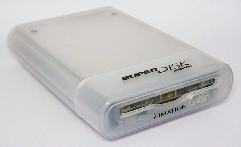
The Imation SuperDisk LS-120 drive featured an auto eject mechanism and as a bonus could read standard floppy disks. You can easily get one of these drives by buying the USB version and removing the drive from the case. The unit fits nicely inside the Portable floppy bay. The issue is that it’s power hungry, requiring 2.7A. That’s almost the entire capacity of one of the UPS modules.

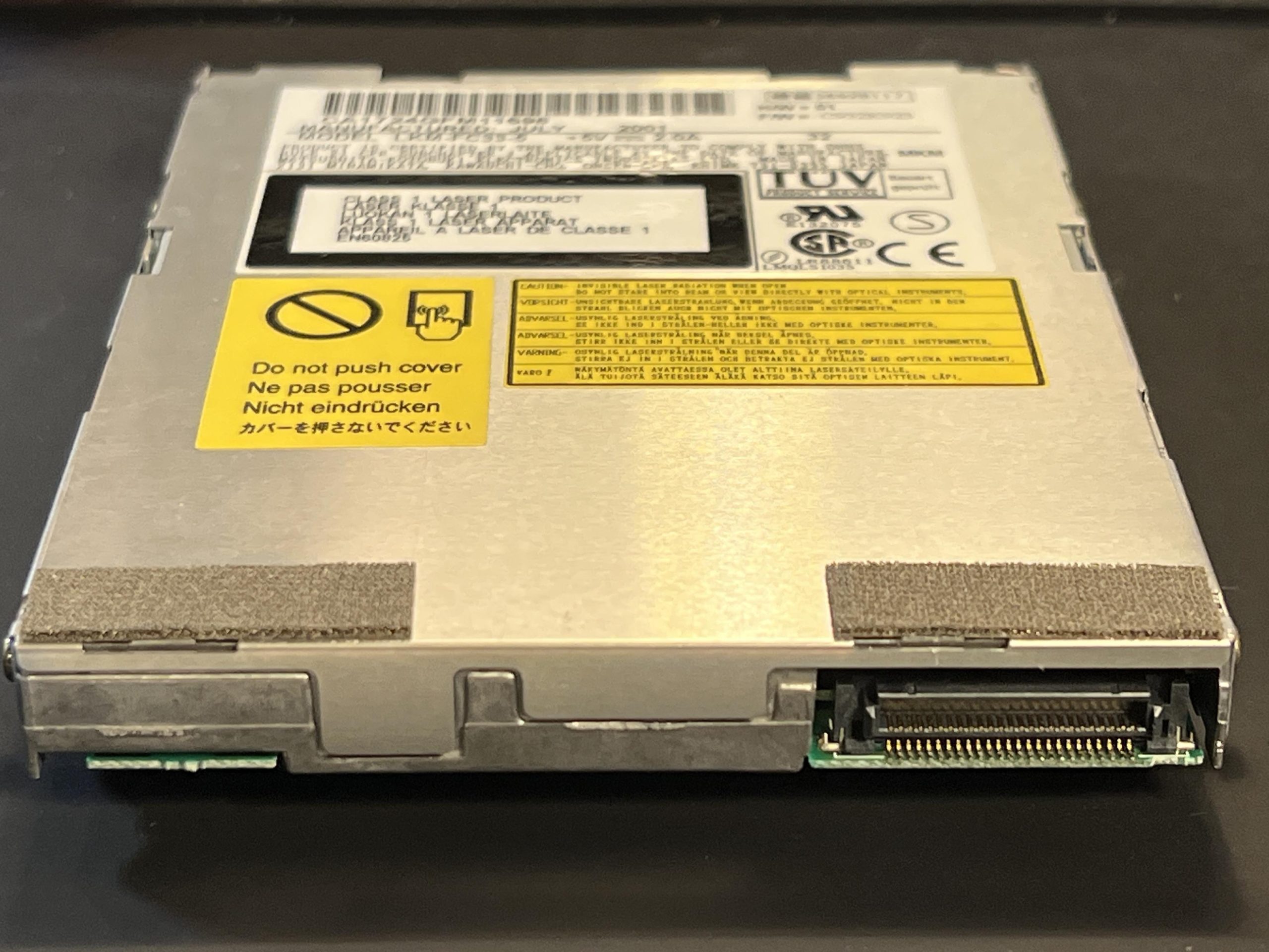
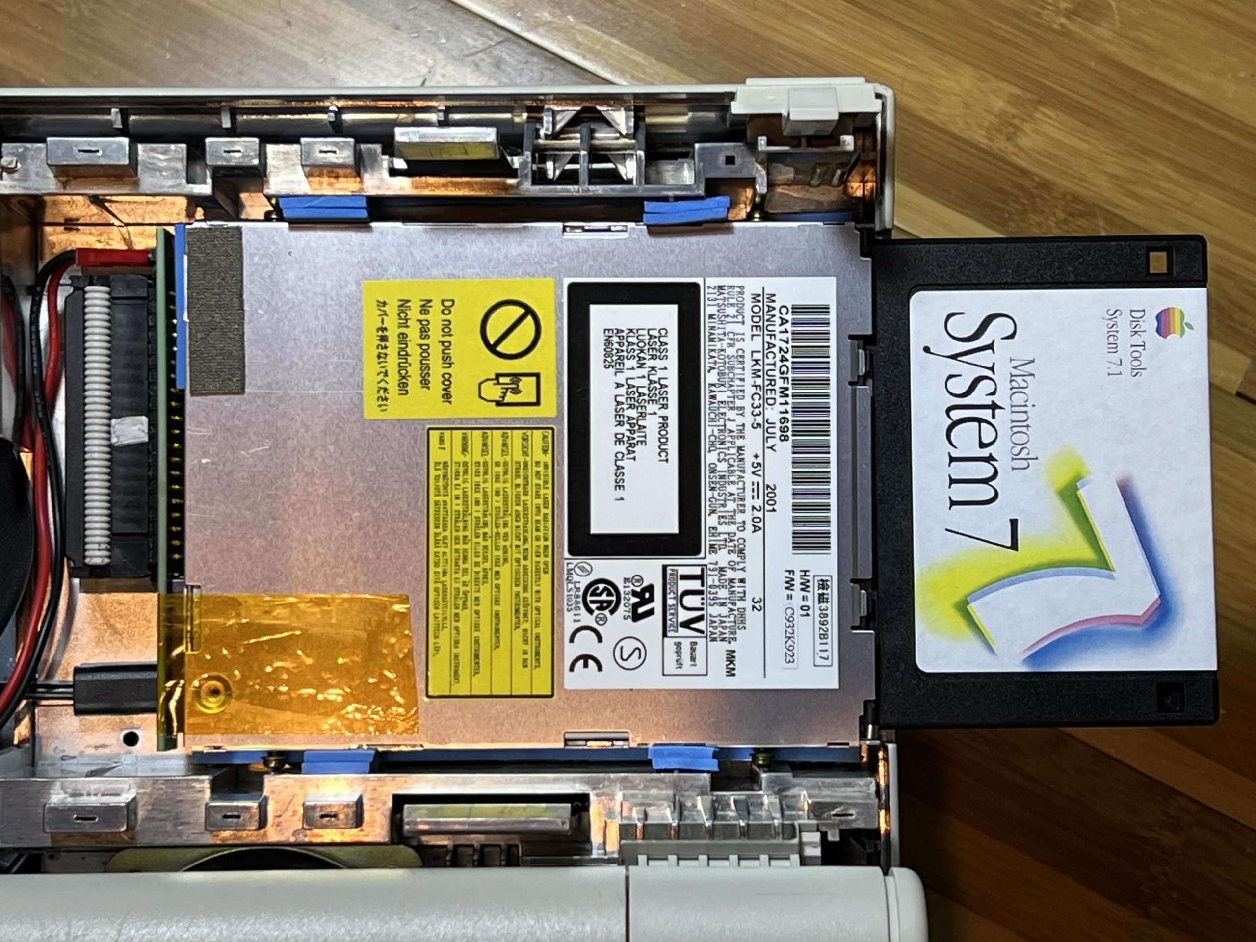
I then remembered that some laptops had a SuperDisk drive built into them. The Panasonic LKM-FC33-5 is exactly that. It’s a slim floppy drive meant for a laptop and is rated at 2.0A instead.
However, interfacing the drive is a challenge. On the back is a familiar 50-pin JAE connector that you may have seen on laptop CD/DVD drives. You might be tempted to use one of those ubiquitous adapter boards to connect it to USB. You’d be wrong! Don’t do this! Panasonic chose a completely different pinout for the drive, however the 50-pin JAE connector is the same.
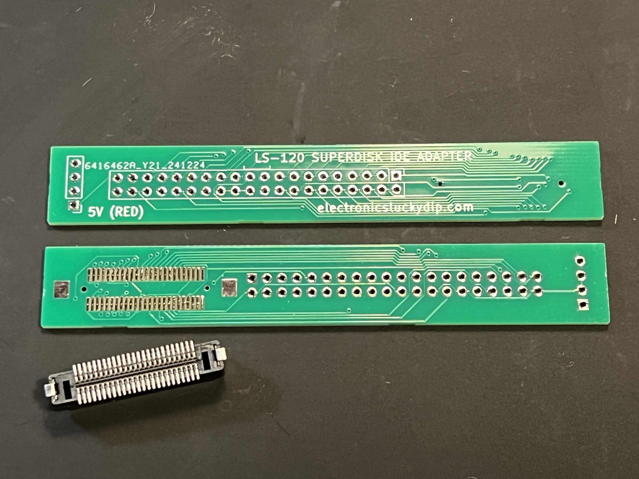
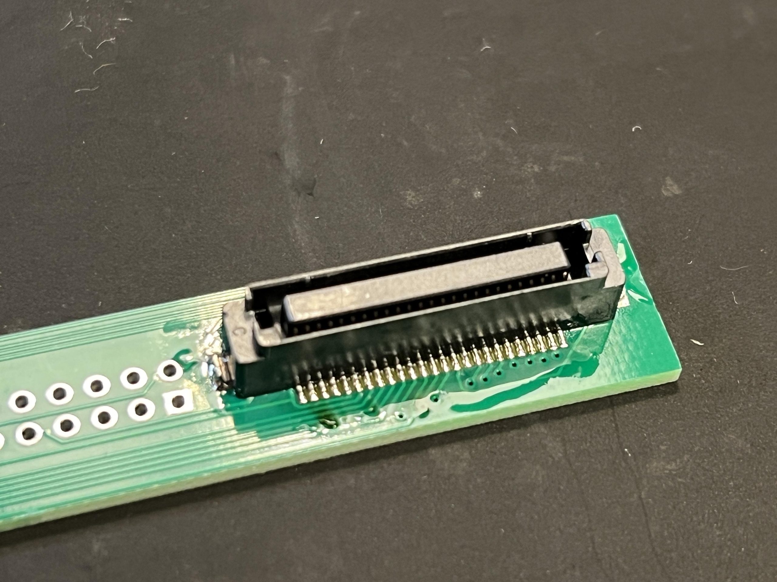
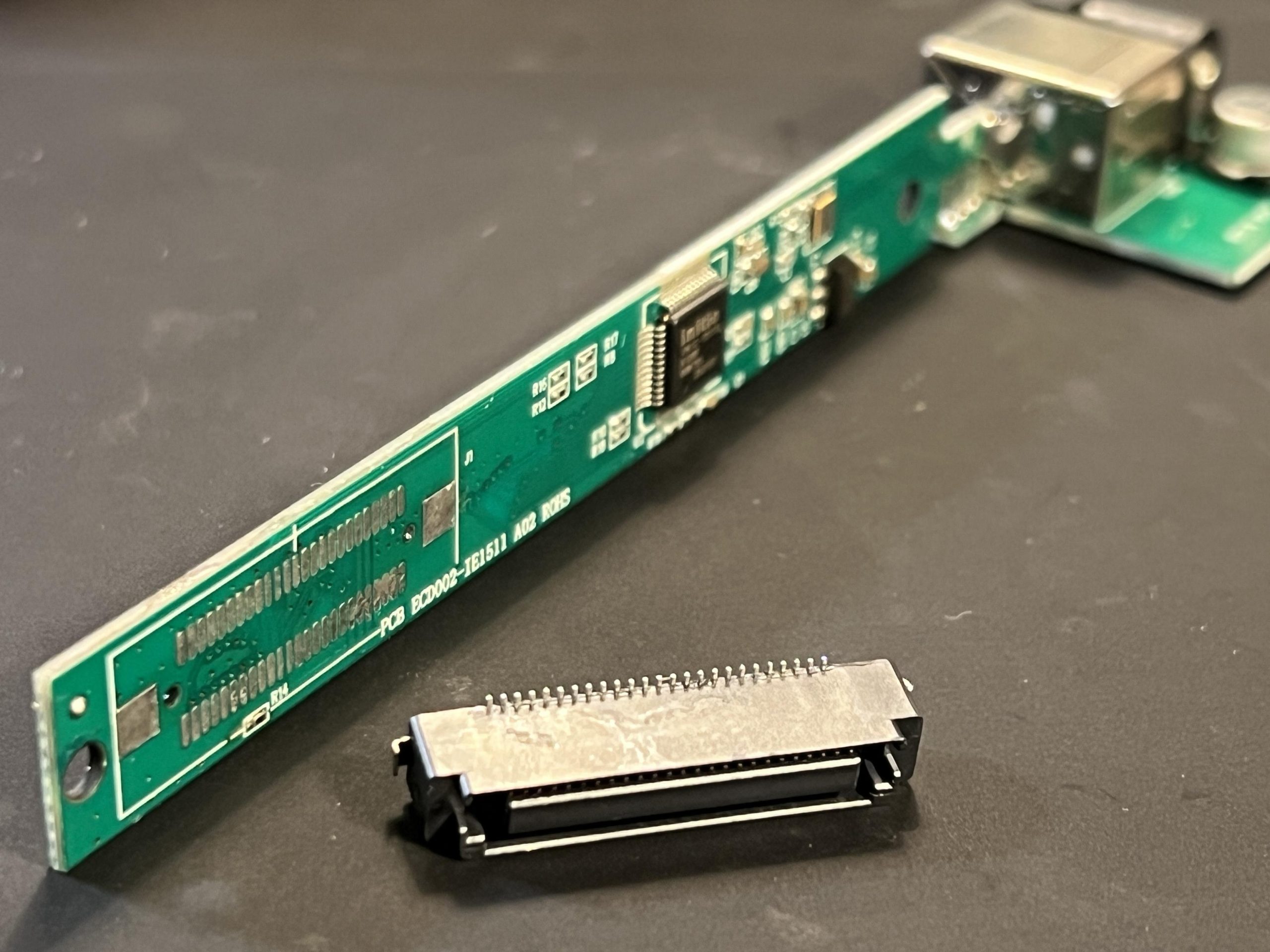
Thankfully, this has all been figured out and documented in this Vogons post. There’s even a new interface board that you can order to convert it to a standard 40-pin PATA connection. I harvested the 50-pin JAE connector from a standard laptop CD drive adapter board.
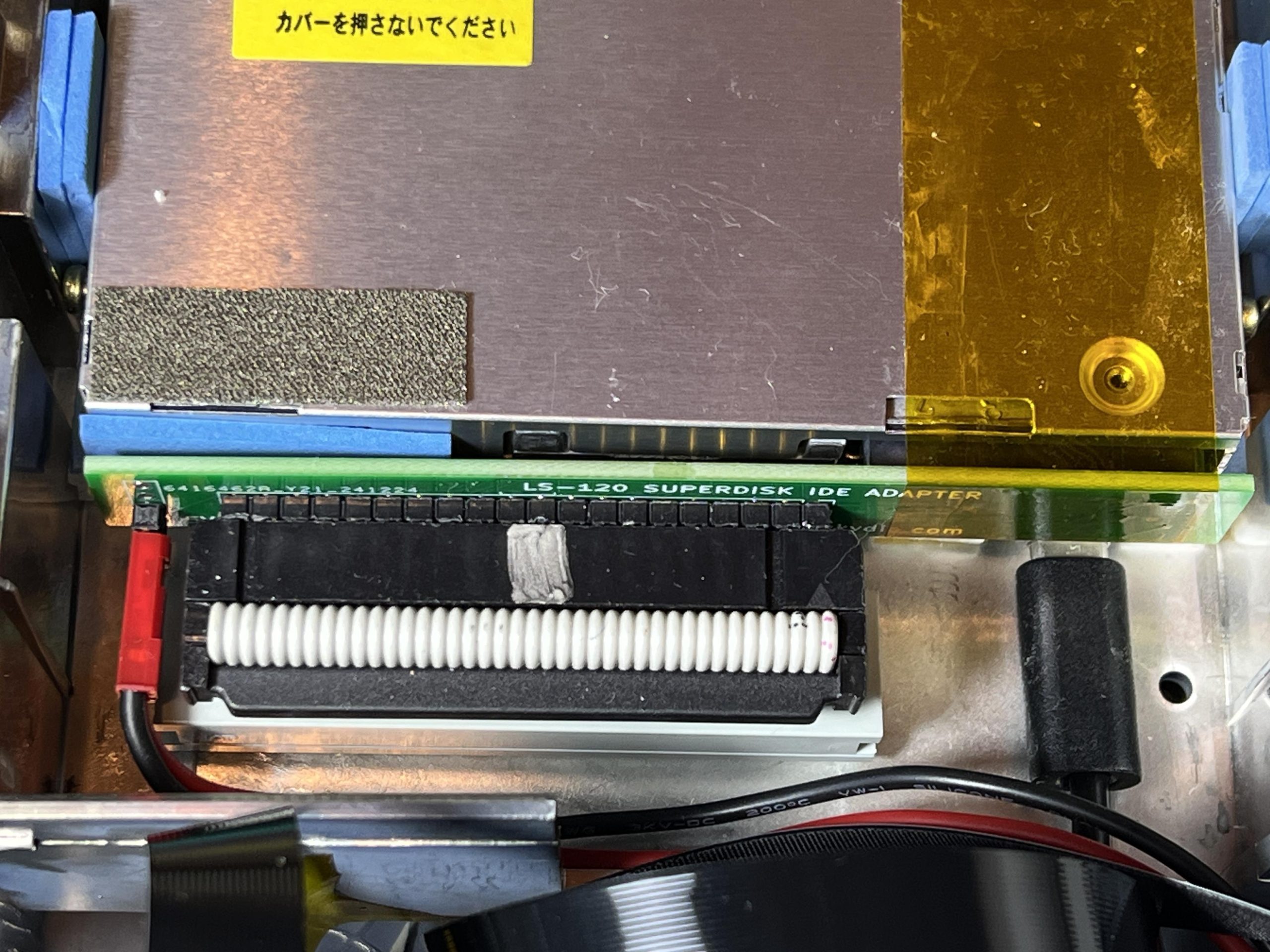
To get that connected to USB, I used an old PATA to USB adapter cable that I cut to length and mounted below the drive itself with a short length of 40-pin ribbon cable and two connectors to make an extension cable. This has the added benefit of seating the drive at the right height for the opening.
Keyboard
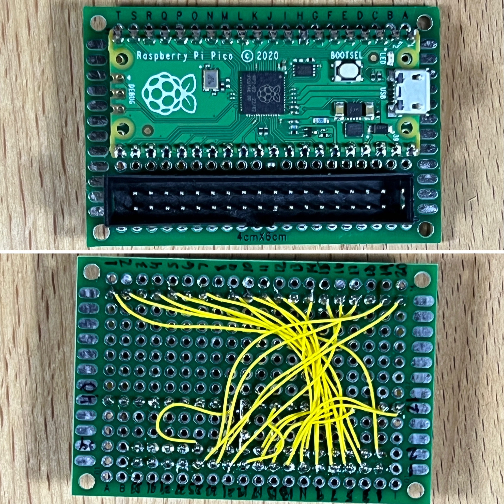
I interfaced the original keyboard using a Raspberry Pi Pico and KMK firmware. I also created a custom board that accepts the ribbon cable from the keyboard. All of this connects to the Pi via a USB cable.
The caps lock key serves as a layer modifier. When it’s locked, the number keys become function keys, up/down arrow keys are volume, backspace is mute toggle, and return is print screen.
I also included a bit of code in the keyboard controller that checks for the space bar being held at power on. This will trigger Circuit Python to mount the CIRCUITPY USB storage drive. The existence of this drive is checked in a startup script and if found it will not launch the emulator.
Install CircuitPython firmware to the Pico, then copy the KMK files to the CIRCUITPY drive of the Pico. Finally, copy the boot.py and code.py files from my ZIP file (linked at the end of the article) to the CIRCUITPY drive of the Pico. The pinout mapping I used is also available in the code.py file.
Trackball
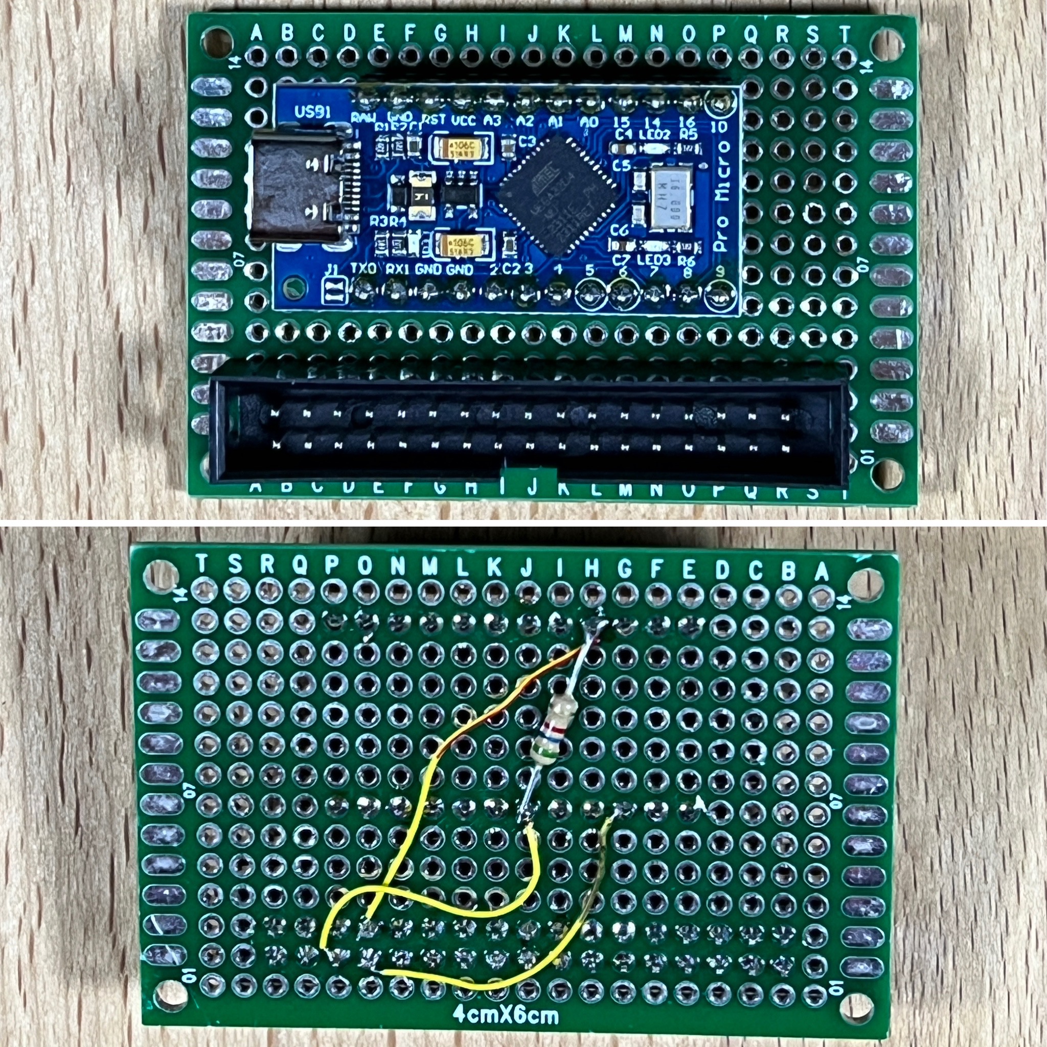
The original trackball is ADB and built by Logitech. It’s nearly identical in design and parts as the Apple Desktop Bus Mouse. I interfaced it with the Pi using a ATmega32u4 5v 16 MHz Pro Micro and followed this excellent writeup in Tinker Different. You can also find a pinout of the trackball in this 68kmla post to locate the ADB, +5V, and GND connections to the ATmega32u4.
The trackball also had some issues and wouldn’t move X direction. It turned out to be either bad IR emitters or detectors. I borrowed a set from an Apple Desktop Bus Mouse.
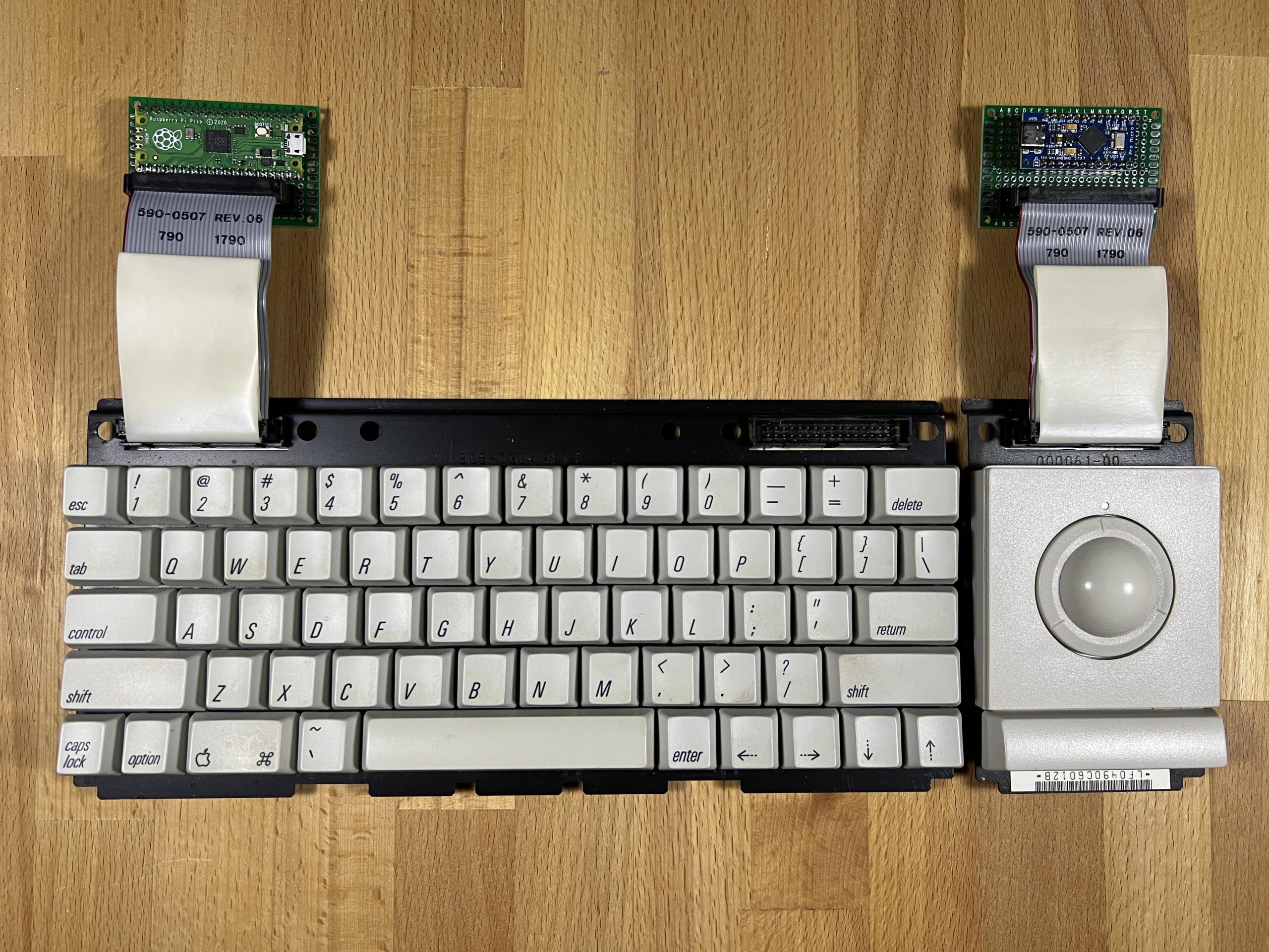
Both and keyboard and trackball use the original 34-pin ribbon cable connectors to attach to the interface boards.
Battery
I wanted to portable to be able to run the Portable from battery as well as be plugged in to be charged. I experimented with using various USB battery packs that fit inside the battery compartment. These worked, however they had shortcomings. The fit was very tight and required the use of right-angle USB cables. Additionally, if you plugged in power to charge the battery, it would cut power output immediately. That doesn’t make for a nice portable experience.
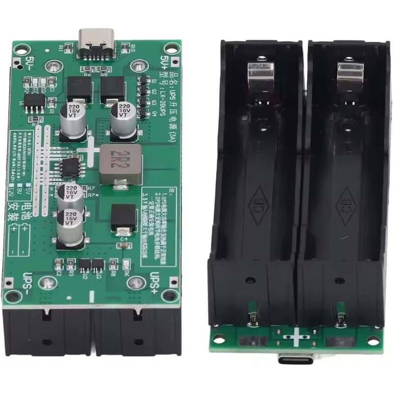
After reading this excellent write up, I settled on using two of these LX-2BUPS mini UPS 5V out modules. They each can hold two 18650 batteries, provide up to 3A at 5V each, and will provide power and charge simultaneously. I used these 20 AWG JST connectors for power connectors, soldering them to the pads on the mini UPS (UPS+ and UPS- are power out and 5V+ and 5V- are for charging the batteries).
Note: I’m not using the built-in USB-C ports on the mini UPS.
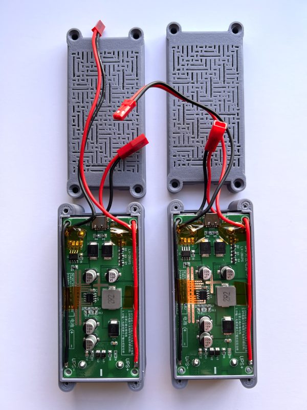
I also printed a case for each of them. The case needed a bit of modification inside to accommodate the wires. One will power the Pi solely and the other will power both the LCD and the floppy drive. Perhaps the outputs can be connected in parallel? I’m not an EE so I don’t know if that will work. For now, I’ll keep them separate.
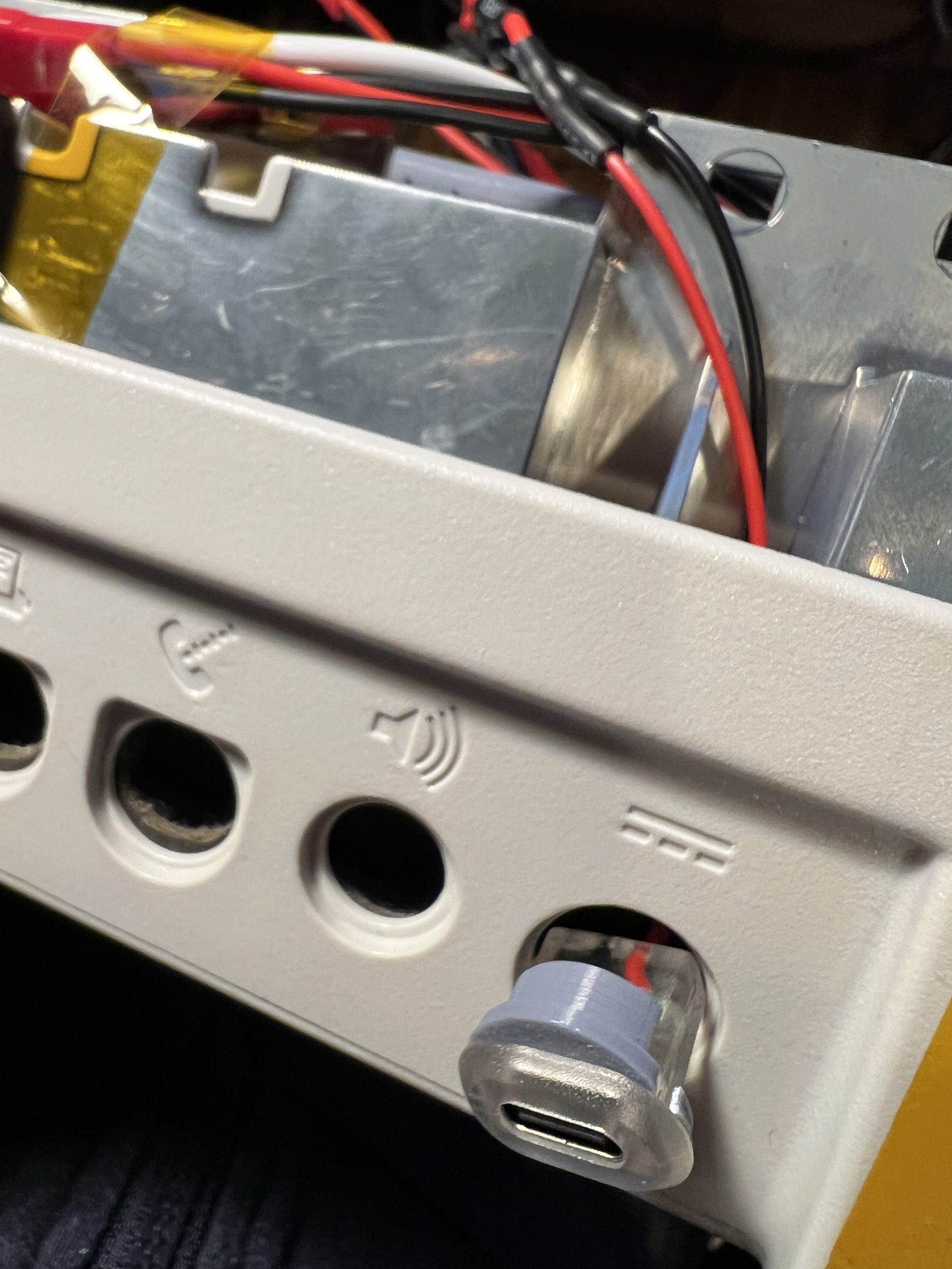
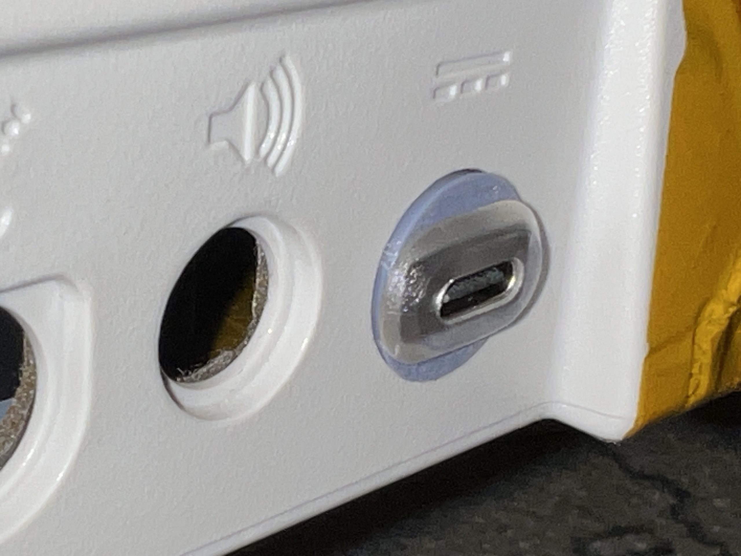
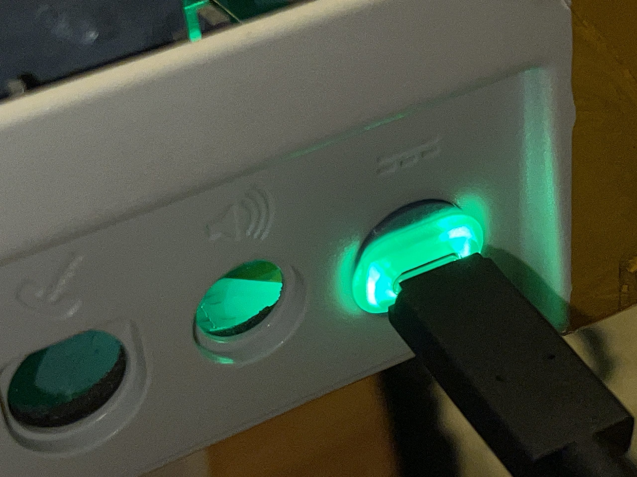
To charge the batteries, I used a USB-C port (after cutting the side clips off) on the rear of the Portable. To hold it in place, I designed and printed a small bezel. This particular port lights up green when connected to power but is not an indication of charging complete, unfortunately. It connects to both of the 5V input ports on the mini UPS modules. In charge mode, I measured an input current of around 1.7A through the USB-C port charging both packs.
I chose these 18650 batteries which have 3300mAh of capacity. I probably should have gotten the flat top variety. The button top variety did fit but it was a very tight fit.
Sound
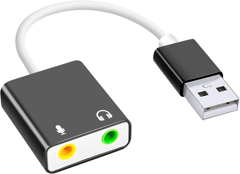
Since the Pi 5 doesn’t have a standard analog audio output jack, I used a simple USB audio device. I connected the Mac Portable’s original speaker to it using a 1/8″ headphone jack. It’s not very loud, but still very audible. Besides, the speaker sounds terrible so I don’t want it to be any louder. Connecting additional speakers and headphones is best done via Bluetooth.
Rear ports
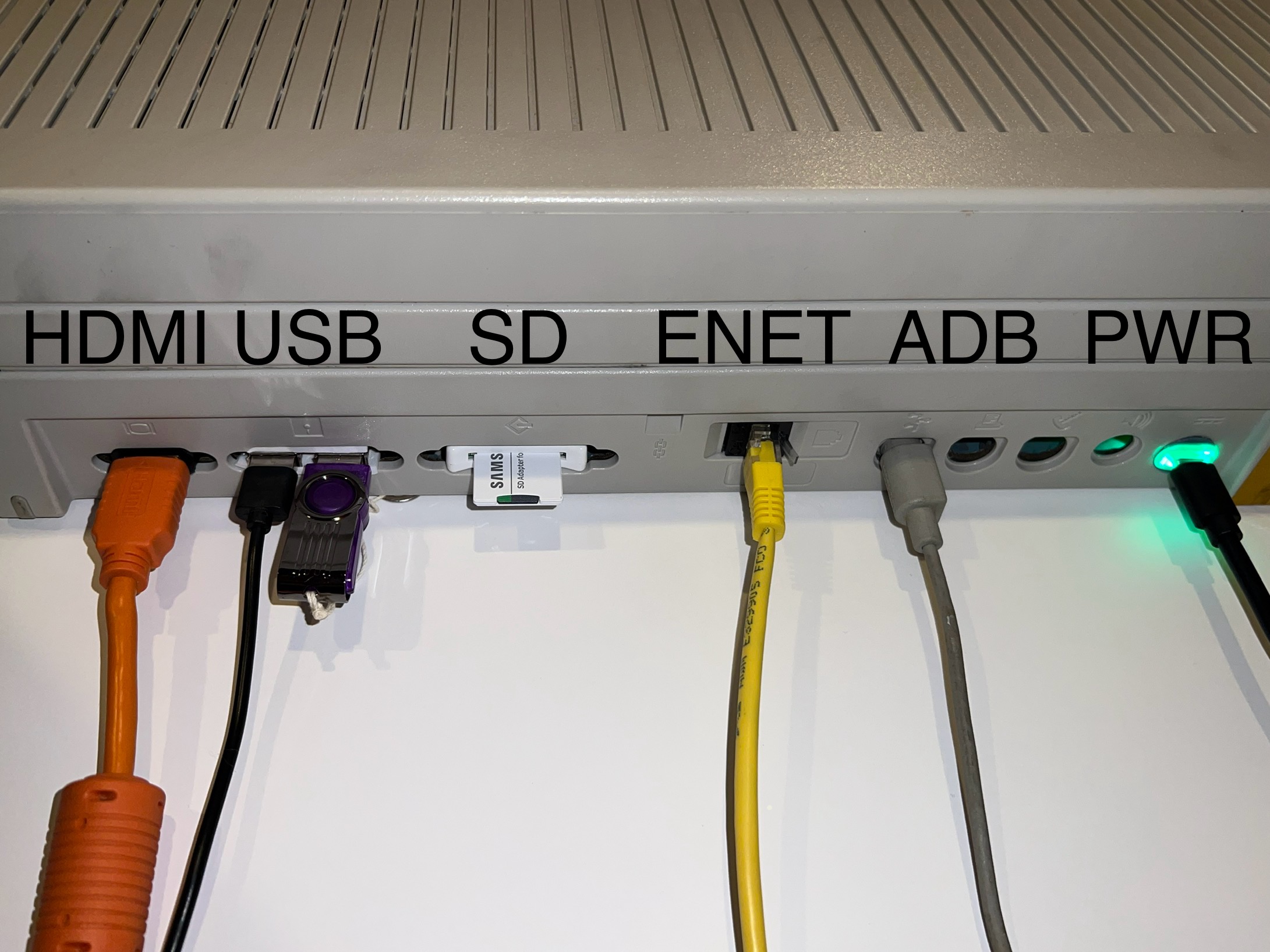
USB: I used two 4 port USB hubs located inside the base of the portable. One provides connectivity for the floppy, keyboard, trackball, and audio. The other provides connectivity for the the two external ports on the back (routed through the old floppy port opening) plus the SD card slot.
HDMI: Since the Pi 5 has two HDMI ports, I ran a second cable from HDMI 2 to rear of the Portable so I can drive a secondary monitor. The port on the back is an HDMI coupler where the original 15 pin D-SUB monitor connector was.
ADB: To connect a ADB mouse or keyboard, I included a second USB to ADB adapter but mounted it to a standard 4 pin mini-DIN female port on the rear (in the original ADB opening).
Ethernet: I ran a small Ethernet cable from the Raspberry Pi 5’s port and plugged it into a keystone coupler. The coupler is hot-glued into the modem port opening.
SD Card: I mounted a USB to SD card reader into the SCSI port opening.
Charge: As previously mentioned, to charge, a USB-C connector is mounted where the original power supply port was.
Software setup
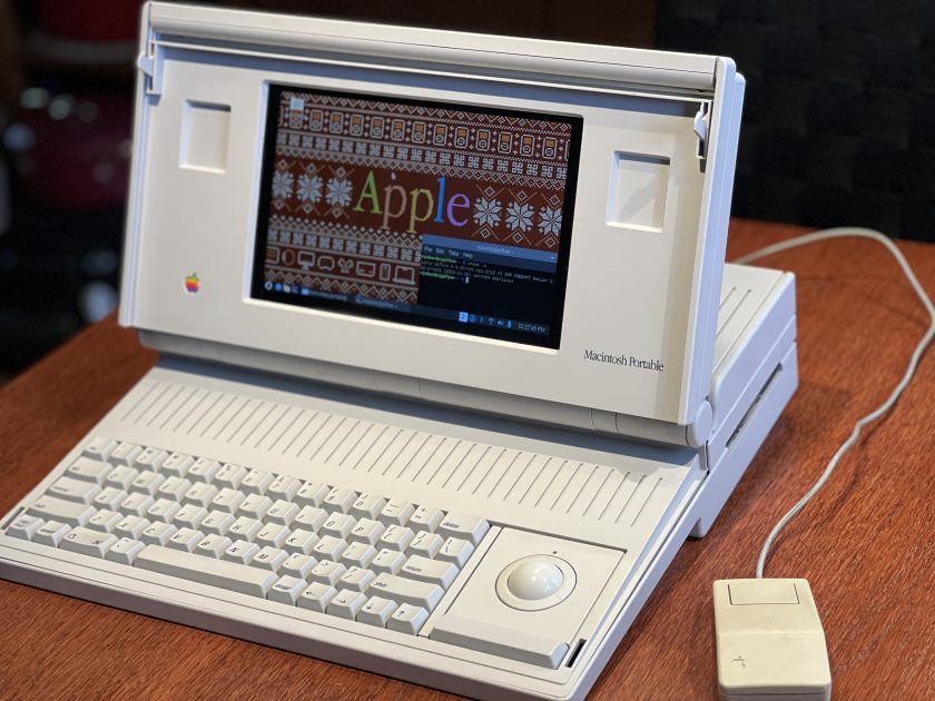
To complete the illusion of a color Macintosh Portable, we need to do some tricks. I’ve chosen to build everything in my home directory on the Pi in a folder named “mac” and the account is set to auto login to the desktop.
Screen size
First, we need to resolve the screen size. I spent weeks trying various different incantations of xrandr. Some would get close, but left the screen in the wrong position, or the menu bar wouldn’t be visible at the bottom anymore. In the end, this is what worked and was placed in /usr/share/dispsetup.sh.
xrandr --output HDMI-1 --mode 1024x768 --rotate inverted
xrandr --setmonitor HDMI-1~1 1024/304x640/190+0+64 HDMI-1
The top and bottom of the screen are still accessible, but windows will full-screen inside a 1024×640 space. Perfect.
Floppy permissions
To be able to eject the floppy, we need to have root access to it. Instead of running everything as root, I simply change the permissions of the floppy device. But this needs to be done on each disk insert as it seems the permissions revert on eject. This script is launched via /etc/rc.local (so it runs as root) and continuously and quietly sets the permissions every minute.
#!/usr/bin/bash

while true
do
	chmod -f 777 /dev/sda
	sleep 60
done
Note: If you boot with another drive attached (like USB) then it may get assigned /dev/sda so its best to boot without any extra drives attached.
Macintosh emulation
I used Mini VMac as the Mac emulator (I used build 2024.06.08 patched by Eric Helgeson) and made some modifications to the source to accomplish the following.
- In CONTROLM.h: Disable the menu pop-up screens when you press the control key and the ‘s’ key. This allows us to inject keyboard commands via scripts without it being visible.
- In COMOSGLU.h: Send text via STDOUT when a disk is ejected from the emulator. This allows us to eject a real disk.
- In ROMEMDEV.c: Remove the ‘V’ from the default disk icon. This was just cosmetic.
These three files can be found in the downloads at the end of the article.
I then used the following commands to build Mini VMac from source on the Pi 5. They enable LToUDP networking, 1:1 speed, sets the resolution to 1024×640 and swaps the Command and Option key. YMMV.
cd minivmac
make clean
gcc setup/tool.c -o setup_t
./setup_t -t larm -cpu a64 -m II -speed z -abr 0 -lt -lto udp -fullscreen 1 -hres 1024 -vres 640 -emm 0 -iid 1 -km Command Option -km Option Command > setup.sh
chmod +x setup.sh
./setup.sh
make
Move or copy the resulting “minivmac” executable to your ~/mac directory.
Startup script
At desktop startup, a script named start-minivmac.sh is launched from ~/.config/autostart that will do the following.
- Check to see if the drive CIRCUITPY exists (remember the holding the space bar trick on the keyboard I added?) If it does, don’t launch the emulator.
- Use ping to wait until the network is up and working. WiFi can take a few seconds to connect.
- Use lsusb to wait until the audio device is up and working. We want to hear the Mac chime!
- And finally launch the emulator via a wrapper.
#! /usr/bin/bash

# Check to see if we started in dev mode (hold space at startup).
# Stop and do not proceed to launching MiniVMac
if mount | grep CIRCUITPY > /dev/null; then
  exit 0
fi

# Wait until network is up
until ping -4 -c1 google.com 2> /dev/null
  do sleep 1
done

# Wait until USB sound is up. Use lsusb to get your adapter's
# USB manufacturer and product IDs for below.
while true
  do
    if lsusb |grep -q "0020:0b21"; then
      break
    fi
  sleep 1
  done
sleep 1

# Start minivmac floppy wrapper
cd ~/mac/
./monitor-floppy.py > monitor-floppy.log
Wrapper to mount and eject floppies
To knit the emulated floppy with the real floppy, I used a Python script to launch Mini VMac, virtually press some keys during the Mac startup, watch for real floppy that are inserted into the SuperDisk drive, and watch Mini VMac for disks being ejected.
This build of Mini VMac supports LToUDP which allows it to access AppleTalk shares, given you have the proper router set up for it. See my post on how to build a classic Mac support server. This will only be successful if the emulator is set to 1x speed on startup. After startup (about 40 seconds on my image), the emulator can be switched to any speed. This script will switch the emulator to “all out” speed after 40 seconds automatically.
To monitor if a real floppy disk is inserted, we monitor dmesg for the following.
sda: detected capacity change from 0 to 2880When this occurs, we wait a few seconds and then send a virtual keyboard stroke of control-2 using xdotool. What does this do? Mini VMac has a feature of drive shortcuts named disk1.dsk, disk2.dsk, etc. Each of those are mapped to control-1, control-2, etc. So we simply create a symlink for disk2.dsk to point to /dev/sda.
cd ~/mac
ln -s /dev/sda disk2.dsk
And voila! The disk you inserted now shows up in the emulated Mac. Caveats are that this only works for 1.4MB Mac disks and will not work for 800K disks.
When you’re finished with the disk in the emulator, simply drag it to the trash. Mini VMac will send “Eject Sony Disk” via STDOUT at which point the Python script picks it up and issues the system eject command.
eject /dev/sdaClever programmers can likely have Mini VMac do all of this for us, but I’m not that clever.
You could likely use the same for CDs or even DVDs. I don’t have any 120MB SuperDisks but they would likely work with this method (although the string to watch for in dmesg might be different).
What’s missing?
Things that I’d like to add in the future.
- There’s no easy way to control the power of the system. I’d like to wire a power switch to the Pi to the switch on the left side of the portable. A bonus would be to figure out a way to power on the system like the original: press any key on the keyboard.
- There’s no way to know how much power is left in the batteries.
- The WiFi signal reception isn’t great, likely due to the inside of the Portable’s plastic case metallic coating.
- An external headphone jack that will silence the internal speaker.
- Emulate a right-click using the trackball’s single button and the keyboard (maybe the control key?).
What’s the weight now?
The original Macintosh Portable M5120 weighed around 16 pounds. My new stealth case mod weighs a little over 9 pounds!
Downloads
Below is a link to download the set of files mentioned in this article. They are definitely not unpack and run. Step through the article and perform the changes as I did using the files provided.
Macintosh Portable Pi.zip (29k)
Thanks
Thank you for taking the time to read the article. Let me know if this inspires you to build a case modded Macintosh of your own.
Richard
March 20, 2025 at 3:05amI have been wanting to run MiniVmac on an RPi for several years now, but always come down to the problem of reading all my old 800K floppy disks from my Mac Plus (with external floppy drive also). I did not fully understand, and am confused by your picture showing actual Mac system 7 floppy drives. I want to stop at system 6.04 (6.07?), the last one before the upgrade to the system 7, which was a giant change that bogged down the MacPlus and made lots of previously fine software no longer workable. I have a lot of old system 6.04 software I want to run, but I must be able to read and load it from an 800K floppy disc.
Are you saying that you managed to get the floppy drive you used to actually read the old 800K Mac floppy disks and directly take the data into MiniVmac on the Pi?? That is what your video seems to show. It was not obvious how you did the code and hardware to make that happen in your description.
Please help me out here, since this is the major sticking point, and i have literally a few hundred old mac floppies containing still valuable data and files, and need to be able to get the data off the Mac floppies and onto more modern media.
Thanks,
Richard Franklin
paulrickards
October 26, 2025 at 9:47amUnfortunately, there’s no way that I know of to read and write 800k Mac floppies using a USB based floppy drive at a file system level and make them usable in MiniVMac live. The disks you see in the video are HD 1.4MB floppies.
From the article: “Caveats are that this only works for 1.4MB Mac disks and will not work for 800K disks.”
Your best bet is to use real hardware and image those disks using Disk Copy and use those in an emulator. Hope this helps.