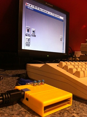
C64 USB Keyboard works with iPad


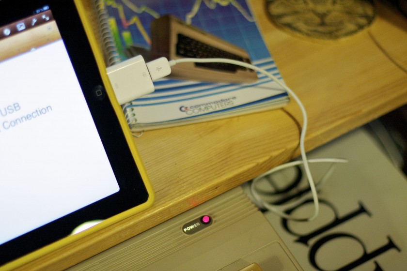
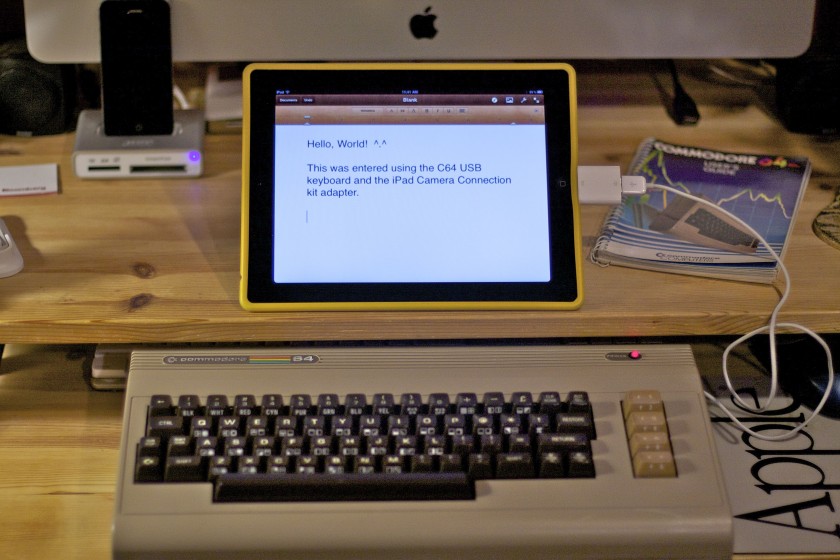
Just a follow up to the C64 USB keyboard Arduino project that I made last week. I was curious if it would work on the iPad using the iPad Camera Connection kit. So I tried it out and was greeted with the error “Cannot Use Device” and “The connected USB device is not supported.” I dismissed the window and tried anyway and it worked! I was able to type in any application.

Any application that is except the Manomio C64 emulator on the iPad/iPhone. I doubt that any USB keyboard would work there, not just mine. Maybe support for USB keyboards could be added?

Commodore 64 Keyboard Gets The USB Treatment Thanks to Arduino

Recently I’ve been repairing a batch of broken Commodore 64’s that I scored on eBay for cheap. Out of the repairs, two boards were beyond hope but still had some usable parts on them so motherboards became donor boards. That left me with a couple empty cases and keyboards so I decided to make a Commodore 64 USB keyboard.
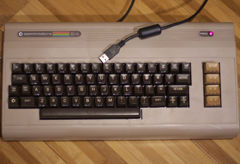
There’s already a nice product called Keyrah that does just this (plus a lot more) and I recommend you checking it out as it adds Amiga keyboard and joystick support.

But if you’re like me and want the challenge, I decided to go the maker route.

First, I searched for any such projects– no sense in re-inventing the wheel. I found a project by Mikkel Holm Olsen called C64 USB Keyboard. It used an Atmel ATMega-8 chip which I’ve learned is very similar to Arduino’s 168/328P chip. It might work but with some modifications– beyond my skill set today. I shelved this project and continued.

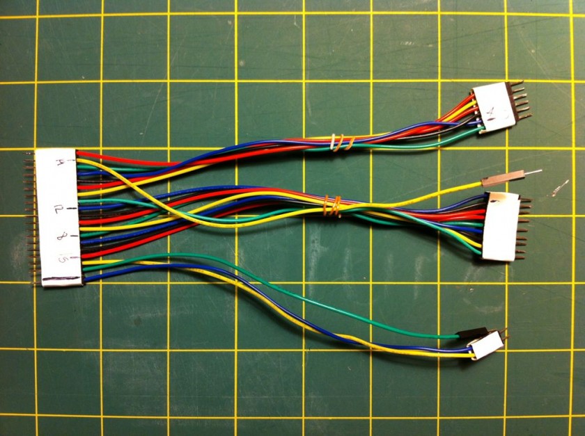
The keyboard is basically an 8×8 matrix keypad. There’s already a keypad library for Arduino. A couple of things that I discovered while using this library. One, don’t use pin 13 with the C64 keyboard. It’s probably because of the built in resister and LED that causes the pull ups to not work. An outside pull up might fix this. Two, the library only supports single keypresses. This is a bummer since you often will press two keys (i.e. the shift key, control, etc). But I worked around it. I put together a quick harness that will connect the Commodore 64 keyboard to the Arduino, aligning the rows and columns to the right pins. I like to make my projects the least destructive way so I use a lot of tape, jumpers and breadboards.
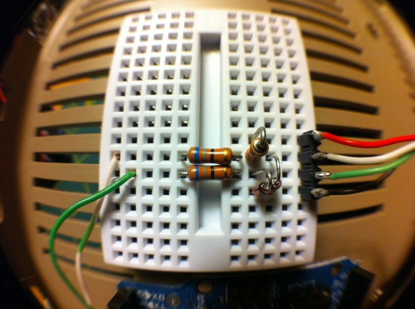
Getting the Arduino to talk USB makes use of the V-USB library which has been ported to Arduino. I really like this implementation because it’s all handled by the Arduino and needs very little passive glue on the outside to make it work. Below is a diagram of how to hook up USB to the Arduino. The values on the diodes are pretty strict and must be 3.6V 500mW zener diodes (although I hear 250mW is better). More information can be found in the V-USB documentation.

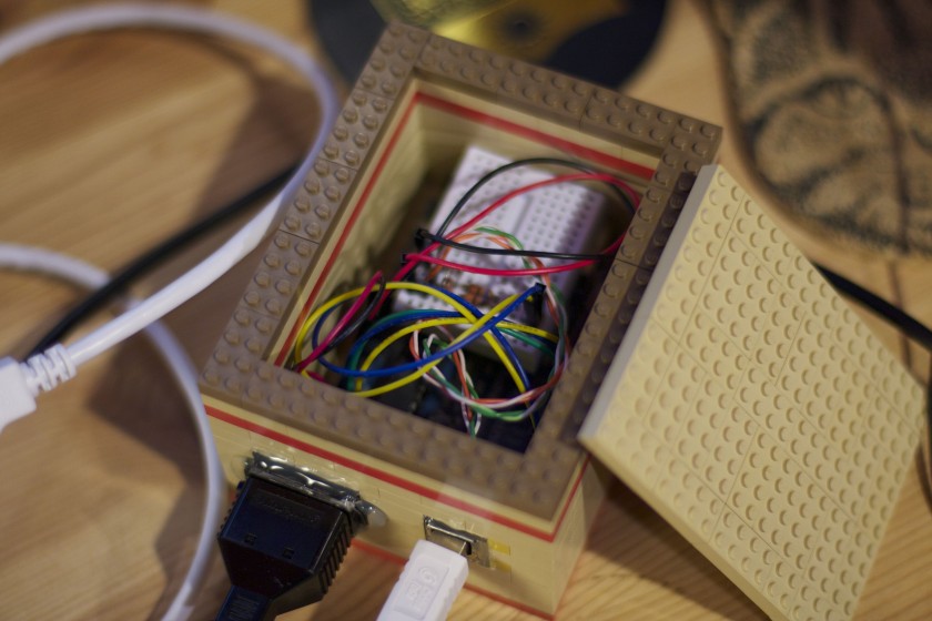
I made a small change to the V-USB code and moved the USB data (-) from Arduino pin 4 to pin 3– just edit usbconfig.h inside the UsbKeyboard library. I also commented out the optional connect/disconnect on pin 5 because I simply don’t have the pins to spare! Connected, the inside looks like this.
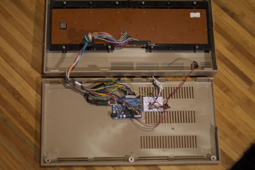
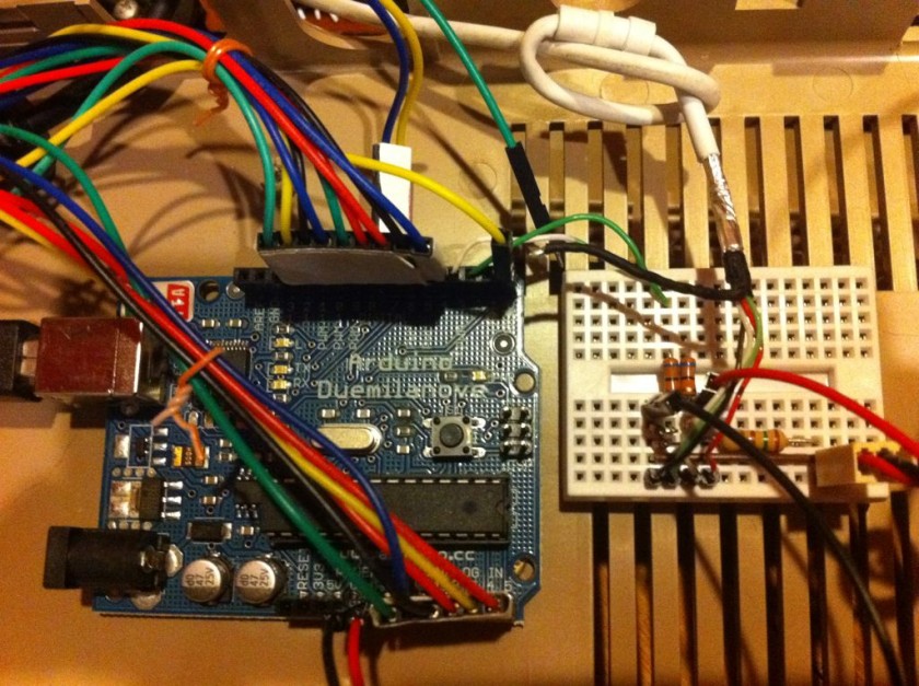
Commodore 64 USB Keyboard Inside

Commodore 64 USB Keyboard Arduino

Arduino V-USB Glue

The pin mapping goes like this:
C64 Pin Arduino Pin
Column 0 = 13 -> 4
Column 1 = 19 -> 5
Column 2 = 18 -> 6
Column 3 = 17 -> 7
Column 4 = 16 -> 8
Column 5 = 15 -> 9
Column 6 = 14 -> 10
Column 7 = 20 -> 11
Row 0 = 12 -> 12
Row 1 = 11 -> 0 (This was pin 13 if you’re wondering why the break in continuity)
Row 2 = 10 -> 14 (Analog 0)
Row 3 = 5 -> 15 (Analog 1)
Row 4 = 8 -> 16 (Analog 2)
Row 5 = 7 -> 17 (Analog 3)
Row 6 = 6 -> 18 (Analog 4)
Row 7 = 9 -> 19 (Analog 5)

I power the Arduino via the incoming USB. To get it to be recognized properly by your computer, unplug the USB programming cable from the Arduino and then plug in the USB cable to the V-USB side. Otherwise it will not be recognized. It makes for a lot of cable swapping unfortunately while coding. I also powered the C64 power LED for nostalgia (this may be a good use for pin 13).

Speaking of code, I needed to define some key codes that were missing from the UsbKeyboard library. This was fairly straight-forward by looking them up on the USB HID guide (chapter 10). I also defined “bogus” key codes that I could intercept and do something else with. Most keys on the keyboard can be passed straight through. Others, like the arrow keys, F-keys, quote, asterisk, etc need a little more help since their locations are different than a standard keyboard. I also hacked together to ability to detect a modifier key (shift, control, etc) along with another key (from the keypad library). The resulting code isn’t pretty but I think it’s easy enough to follow. It’s included below for your amusement.

This project is far from perfect but it’s a start.


#include <Keypad.h>
#include <UsbKeyboard.h>

// Define keys that are missing from UsbKeyboard.h
#define KEY_ESCAPE  41
#define KEY_DELETE 42
#define KEY_TAB 43
#define KEY_MINUS 45
#define KEY_EQUAL   46
#define KEY_LEFTBRACKET 47
#define KEY_RIGHTBRACKET 48
#define KEY_BACKSLASH 49
#define KEY_SEMICOLON 51
#define KEY_SINGLE_QUOTE 52
#define KEY_BACKTICK 53
#define KEY_COMMA   54
#define KEY_PERIOD  55
#define KEY_SLASH   56
#define KEY_INSERT  73
#define KEY_HOME    74
#define KEY_PAGEUP 75
#define KEY_PAGEDOWN 78
#define KEY_RIGHTARROW 79
#define KEY_LEFTARROW 80
#define KEY_DOWNARROW 81
#define KEY_UPARROW 82
#define KEY_AT      206

// Bogus key codes, intercepted in code below
#define KEY_PLUS 249
#define LEFT_SHIFT 250
#define RIGHT_SHIFT 251
#define COMMODORE 252
#define CONTROL 253
#define KEY_COLON 254
#define KEY_STAR 255

const byte ROWS = 8;
const byte COLS = 8;
byte mod = 0;

// Define the Keymap
char keys[ROWS][COLS] = {
 {KEY_DELETE, KEY_ENTER, KEY_RIGHTARROW, KEY_F7, KEY_F1, KEY_F3, KEY_F5, KEY_DOWNARROW},
 {KEY_3, KEY_W, KEY_A, KEY_4, KEY_Z, KEY_S, KEY_E, LEFT_SHIFT},
 {KEY_5, KEY_R, KEY_D, KEY_6, KEY_C, KEY_F, KEY_T, KEY_X},
 {KEY_7, KEY_Y, KEY_G, KEY_8, KEY_B, KEY_H, KEY_U, KEY_V},
 {KEY_9, KEY_I, KEY_J, KEY_0, KEY_M, KEY_K, KEY_O, KEY_N},
 {KEY_PLUS, KEY_P, KEY_L, KEY_MINUS, KEY_PERIOD, KEY_COLON, KEY_TAB, KEY_COMMA},
 {KEY_PAGEDOWN, KEY_STAR, KEY_SEMICOLON, KEY_HOME, RIGHT_SHIFT, KEY_EQUAL, KEY_BACKSLASH, KEY_SLASH},
 {KEY_1, KEY_BACKTICK, CONTROL, KEY_2, KEY_SPACE, COMMODORE, KEY_Q, KEY_ESCAPE}
};
byte colPins[COLS] = {4,5,6,7,8,9,10,11};
byte rowPins[ROWS] = {12,0,14,15,16,17,18,19};

// Create the Keypad
Keypad kpd = Keypad( makeKeymap(keys), rowPins, colPins, ROWS, COLS );

void setup()
{
}

void loop()
{
  UsbKeyboard.update();
  mod = 0;

  // Kludge, find activate modifiers
  // control   [7][2]
  // commodore [7][5]
  pinMode(rowPins[7], OUTPUT);
  digitalWrite(rowPins[7], LOW);
  if (digitalRead(colPins[2]) == LOW) { mod = mod | MOD_CONTROL_LEFT; }
  if (digitalRead(colPins[5]) == LOW) { mod = mod | MOD_ALT_LEFT; }
  pinMode(rowPins[7], INPUT);
  digitalWrite(rowPins[7], HIGH);

  // left shift[1][7]
  pinMode(rowPins[1], OUTPUT);
  digitalWrite(rowPins[1], LOW);
  if (digitalRead(colPins[7]) == LOW) { mod = mod | MOD_SHIFT_LEFT; }
  pinMode(rowPins[1], INPUT);
  digitalWrite(rowPins[1], HIGH);
  
  // right shift[6][4]
  pinMode(rowPins[6], OUTPUT);
  digitalWrite(rowPins[6], LOW);
  if (digitalRead(colPins[4]) == LOW) { mod = mod | MOD_SHIFT_RIGHT; }
  pinMode(rowPins[6], INPUT);
  digitalWrite(rowPins[6], HIGH);
  
  if (mod == 6) {
    UsbKeyboard.sendKeyStroke(0, mod); // This works, but sends 3-4 times. :(
    return;
  }

  char key = kpd.getKey();
  if (key) {
    switch (key) {
      case KEY_STAR:
        UsbKeyboard.sendKeyStroke(KEY_8, MOD_SHIFT_LEFT);
        break;
      case KEY_AT:
        UsbKeyboard.sendKeyStroke(KEY_2, MOD_SHIFT_LEFT);
        break;
      case KEY_PLUS:
        UsbKeyboard.sendKeyStroke(KEY_EQUAL, MOD_SHIFT_LEFT);
        break;
      case KEY_COLON:
        UsbKeyboard.sendKeyStroke(KEY_SEMICOLON, MOD_SHIFT_LEFT);
        break;
      default:
        if (mod == MOD_SHIFT_LEFT || mod == MOD_SHIFT_RIGHT) {
          if (key == KEY_2) { key = KEY_SINGLE_QUOTE; } // "
          if (key == KEY_7) { key = KEY_SINGLE_QUOTE; mod = 0; } // '
          if (key == KEY_6) { key = KEY_7; } // &
          if (key == KEY_9) { key = KEY_0; } // )
          if (key == KEY_8) { key = KEY_9; } // (
          if (key == KEY_DOWNARROW) { key = KEY_UPARROW; mod = 0; }
          if (key == KEY_RIGHTARROW) { key = KEY_LEFTARROW; mod = 0; }
          if (key == KEY_F1) { key = KEY_F2; mod = 0; }
          if (key == KEY_F3) { key = KEY_F4; mod = 0; }
          if (key == KEY_F5) { key = KEY_F6; mod = 0; }
          if (key == KEY_F7) { key = KEY_F8; mod = 0; }
        }
        UsbKeyboard.sendKeyStroke(key, mod);
        break;
    }
  }
}
HOW TO: Make a time lapse movie

I thought I’d share with you how I create my time lapse movies. It’s quite simple and doesn’t require any special equipment, save for a simple video camera.

I use a Flip HD camera that I picked up before they went out of business (someone, please remind me, why did Cisco kill that business again?). It has a maximum recording time of about 1 hour per movie so I can’t make time lapses longer than that so I need to keep that in mind.

I start by setting up the camera on a tripod to keep it stationary– this is very important and is hopefully obvious. Set it to record and don’t move it (unless you want to change the shot). Let it record in real time and capture everything. Don’t worry about the audio, we won’t be using it.

Afterwards, you’ll be left with a huge Quicktime .MOV file. Using Quicktime 7 Pro, open the movie. Make sure the player window hasn’t been resized (hit command-1 on a Mac). This will be important in the next step. Usually the head and tails of your movie will have a slight bit of motion in them so you don’t want that– trim the heads and tails off from the movie if you need to. It’s all under the edit menu. Use the ‘I’ and ‘O’ key to mark in and out points and use Edit->Cut to remove it.

Next, use File->Export. Choose export as “Movie to Image Sequence” and click Options. Change the format to JPEG. The frames per second you choose here will dictate how fast or slow your final time lapse will be. Let’s assume that your source movie is 1 hour. Choosing a small number like 1 FPS will give you a movie that lasts 2 minutes. Choosing 2 FPS will give you 4 minutes and so on. You can also put decimal numbers like .5 or .25 FPS. You can experiment with this value. I call this frame thinning because you are discarding a lot of the original source movie. This is ok. Also, click “Insert space before number.” Click OK. Make a new folder to put these images in (in the thousands for our example). Give it a base name and click save.

The final step is where the magic occurs. Choose File->Open Image Sequence, navigate to the folder and click the first image from the series. The next dialog asks what frame rate. I choose 30 to keep things fluid. Again, choosing a slower frame rate will make your movie longer. Click OK and wait. Once done, you’re rewarded with a great time lapse. Add some music, export to MPEG-4 and share!

DIY Foam Packaging

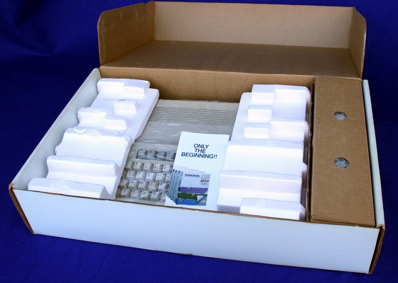
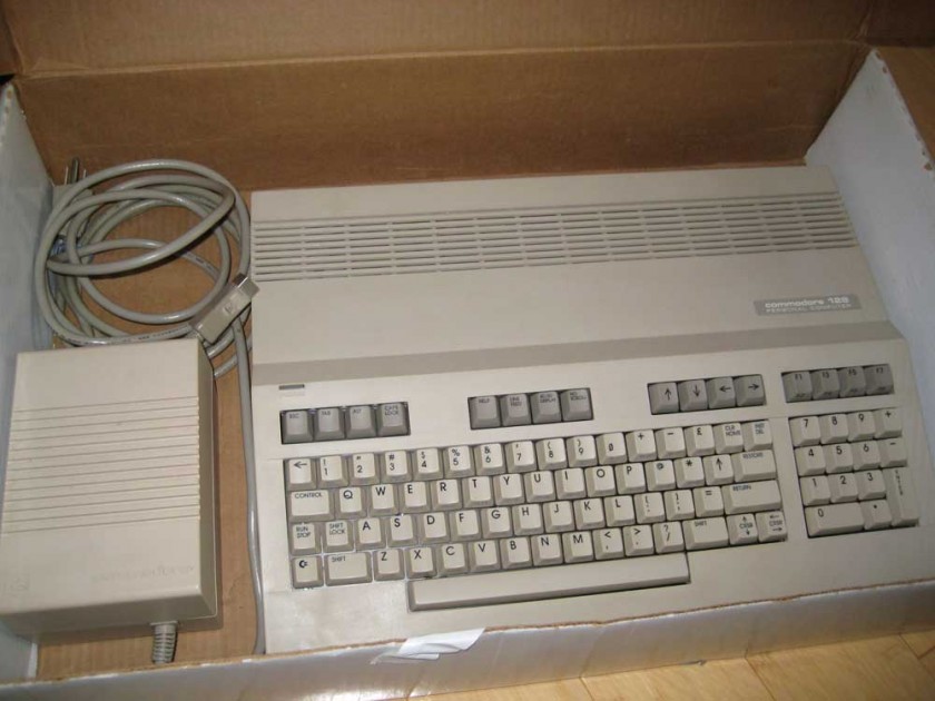
It’s time to de-clutter once and again and that means time to visit eBay. First item I’m parting with is a nice Commodore 128 and 1571 disk drive. I have the original box for the CPU but that’s about it for the packaging. I don’t have the original foam sides that held the computer in place (see picture below).

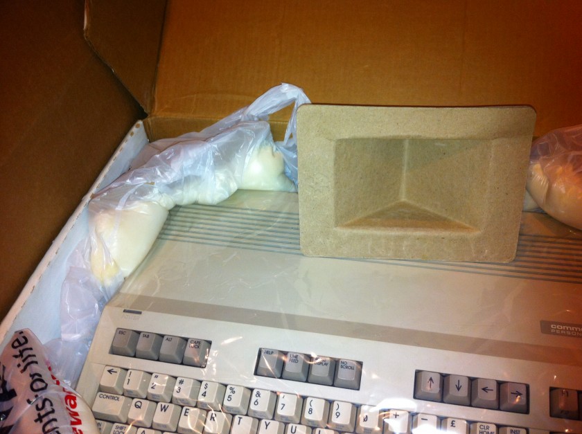
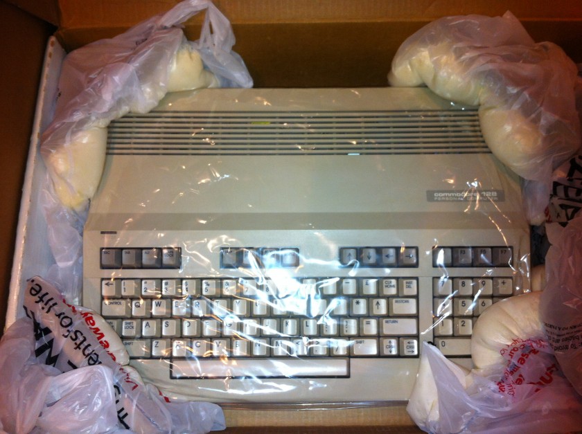
Instead, my computer looks more like this.

I need a good way to keep the computer from getting damaged inside the original box before that box goes in another box– follow me? That got me thinking about the expanding foam in a bag system I’ve seen before. It’s foam that expands inside a plastic bag– place it inside the box and close the lid and it fills the voids and holds everything in place. I wondered if a can of “Good Stuff” expanding foam insulation would work. I picked up a can (large gap filler) for a $5er.

I have these nice cardboard corners as starting points– but they’re a little big. My plan was to fill the corners with foam, put a bag over it and put the computer inside it and let the foam do it’s magic. The results so far look promising.


Some things I’ve noticed–

  • It expands slowly, so don’t rush, you’ve got hours before it cures.
  • Make sure to put at least two pieces of plastic between the foam and your object to keep it safe.
  • Don’t over do it– remember, it will expand.
  • Wear gloves!
  • Some areas seem to be taking a long time to cure. The bottle says water speeds the process.

Converting standard joysticks to wireless infrared for Amiga CDTV and Chameleon 64

The Chameleon 64 is a great cartridge. With each release of the firmware, new features are being unlocked. Recently, the Minimig core was ported to the Chameleon 64 which means you can now have a fully emulated Amiga that fits in the palm of your hand.

To play games using a joystick, you need a CDTV infrared (IR) remote. They are still available for purchase here and here but it would take a few weeks for it to arrive.

I wanted to see if it’s possible to convert a standard joystick to wireless IR communications. I know it can be done– I’ve had some experience using Arduino’s to communicate over IR with a vintage LED sign I have. I reverse engineered the original protocol by using the original remote to the sign. That project taught me a lot.

In this case, I don’t have the remote. So I asked on the forum and got a response from the programmer of the Chameleon IR code with all the info I needed (Thanks Peter!).

This version uses an original Nintendo NES game pad for the joystick but this could be easily changed to support a standard 9-pin Commodore/Amiga/Atari style joystick. The gamepad is connected to the Arduino and decoded into button presses. It then transmits it via infrared signals to the Chameleon. The code uses the Arduino-IRremote library with additions (included) for the CDTV remote type added.

Download CDTV IR Remote

eBay Oddity: Silver Reed EB-50

Silver Reed EB-50 PrinterToday I present to you the Silver Reed EB-50. Made in 1985, this thing has a bit of an identity crisis. It’s a printer, a plotter and a typewriter all in one. The reason I got it was because it uses the same tiny ball-point pens that the Commodore 1520 printer/plotter uses. However, this prints on normal 8.5″ wide paper. It’s also very portable, has a lid that covers the keyboard and a flip out handle. It can run on batteries (5 x D cells OMG heavy) or on DC 7.5V power (center negative in case you want to know). For $9.99 it was a bargain curiosity that I couldn’t pass up.


In normal typewriter mode, you press a key and it will “draw” that character in one of 3 sizes, styles or directions in one of 4 colors. You can position the print head anywhere you’d like to print text. In addition, there are function keys to create graphs, right on the typewriter. Pie charts, bar graphs and line graphs are simple– select the type, enter the data points and it prints a graph at the print head position. Pretty clever for something that works sans computer.

Switch it to printer mode and now a computer takes over via the parallel port. This is where things got weird. I found reference to someone that wrote a program to convert HPGL plotter files to ones that printed on this one. This was key since there was no manual and I ran out of internets. But the file was locked up in a “drivers” ad supported nightmare of a website that had me install some bullshit driver manager on Windows to “install” a C code source file. What-fucking-ever. It’s included below in you want it.


A quick Processing sketch later and I’ve produced some output on it from my Mac using an old PowerPrint serial to parallel adapter via a KeySpan USB to serial adapter. Lots of adaptation, but what do you expect from a nearly 26 year old printer.


# hp2eb50.c
#include <stdio.h>

#define SCAL(x) (((x)+halfscale)/scale)
#define NUMV(x) ((x)=='-' || ((x) <= '9' && (x) >= '0'))
#define SP ('S'<<8)+'P'
#define PU ('P'<<8)+'U'
#define PD ('P'<<8)+'D'
#define PA ('P'<<8)+'A'
#define IW ('I'<<8)+'W'
#define SC ('S'<<8)+'C'
#define LB ('L'<<8)+'B'

FILE *source, *plotter;
short c,i,j,pen,scale,x1,x2,y1,y2,hx,hy,halfscale;
short befehl,ende,rot, colour[] = {0,1,2,3,0,1,2,3};
char param[100], *output;

void upcase(s)
   char *s;
  {
   register char c;
   register int  i=0;

   while ((c = *(s++)) && i<99)
     {
      param[i++] = (c>='a' && c<='z')? c-'a'+'A' : c;
     }
   param[i] = 0;
  }

short get_num()
  {
   register short c,x=0;
   short s;

   if (ende) return(0);
   else
     {
      while(((c = getc(source)) & 0x1ff) <= ' ');
      if (c == '-')  
        {
         s=-1;
         c = getc(source);
        }
      else s=1;
      while (c >= '0' && c <= '9')
	{
	 x = x*10+c-'0';
         while(((c = getc(source)) & 0x1ff) <= ' ');
	}
      if (c == ';') ende = -1;
      return(x*s);
     }
  }

void rotate()
  {
   register short h;

   if (rot)
     {
      y2 = y1;
      h = x1; x1 = y1; y1 = -h;
     }
  }

main(argc,argv)
   int argc;
   char *argv[];
  {
   if (argc<2)
     {
      printf("Usage: %s <hpgl-file> [SCALE <scale>] [ROT] [COLOUR <n1..n8>] [TO <output filename>]n",argv[0]);
      exit(0);
     }

   rot = 0;
   output = "par:";
   for (i=2;i<argc;i++)
     {
      upcase(argv[i]);
      if (!strcmp(param,"ROT")) rot=1;
      if (!strcmp(param,"SCALE") && i<argc-1)
	{
	 scale = atol(argv[++i]);
	 if (scale == 0) scale = 1;
	}
      if (!strcmp(param,"TO") && i<argc-1) output = argv[++i];
      if (!strcmp(param,"COLOUR") && i<argc-1)
	{
	 for (i++,j=0;j<8;j++) colour[j]=(argv[i][j]-'0') & 0x03;
	}
     }
   halfscale = scale/2;

   if (!(source = fopen(argv[1],"r")))
     {
      puts("Sorry - Can't open file!");
      exit(0);
     }
   if (!(plotter = fopen(output,"w")))
     {
      puts("Sorry - Can't open output file");
      fclose(source);
      exit(0);
     }

   pen = 0;
   fputc(18,plotter);  
   puts(" Command no.:");
   j = 1;
   do
     {
      i = ende = 0;

      do
	{
	 c = getc(source);
	} while (((c < 'A') || (c > 'Z')) && (c != -1));
      befehl = (c==-1)? 0 : (c & 0xff)<<8 | (getc(source) & 0xff);

      printf("2331A23313C %5dn",j++);   

      switch(befehl)
        {
         case SP : {
		    x1 = get_num();
		    if (x1)
                      fprintf(plotter,"C%d;n",colour[(x1-1)&7]);
                    break;
		   }
         case PU : {
         	    pen = 0;
		    break;
		   }
         case PD : {
		    pen = 1;
		    break;
		   }
         case PA : {
		    while (!ende)
		      {
		       x1 = SCAL(get_num());
		       if (!ende)
			{
		  	 y1 = SCAL(get_num());
			 rotate();
		         if (pen==1) 
                             fprintf(plotter,"D%d,%d;n",x1,y1);
		           else 
                             fprintf(plotter,"M%d,%d;n",x1,y1);
			}
		      }
		    break;
		   }
	 case LB : {
		    fputc('P',plotter);
	            while((c = getc(source)) >= 32) 
		      putc(c,plotter);
		    putc(13,plotter);
		    putc(10,plotter);
		    break;
		   }
         case SC : {
		    x1 = get_num();
		    if (ende) break; 
		    x2 = get_num();
		    y1 = get_num(); y2 = get_num();		    
		   }
         case IW : {
		    if (befehl==IW)
		      {
		       x1 = get_num(); y1 = get_num();
		       y2 = get_num(); y2 = get_num();
		      }
		    hx = (x2-x1+999)/1000;
		    hy = (y2-y1+999)/1000;
		    hx = (hx>hy)? hx : hy;
		    if (scale<hx)
		      {
		       scale = hx;
		       halfscale = scale/2;
		       printf("New scale: %dn2331A",scale);
		      }
		    rotate();
		    fprintf(plotter,"M%d,%d;nI;n",SCAL(-x1),SCAL(-y2));
		   }
        }
     } while (c!=-1);
   fputc(17,plotter);
   fclose(source);
   fclose(plotter);
   puts("nReady.n");
  }


Testing a Geiger Counter Kit

I recently purchased a Geiger counter kit from Goldmine Electronics. I soldered everything together; attaching the Geiger tube was the trickiest as it’s not actually soldered to the board, just ”
strapped” with some wire in three places. One end of the tube is the positive (+) side and the entire center of the tube is negative (-).

I turned it on but couldn’t think of anything to test it with. It would occationally click every now and then but that’s normal background radiation. Then I remembered I had this bowl in the cupboard. I knew the the old 1930’s Fiestaware red/orange color was radioactive because they used uranium oxides in the glaze. This bowl isn’t Fiestaware but it’s probably just as old.

I won’t be eating from it again.

Print from iPad to ImageWritter II


What if you could print from and iPad to an ImageWriter II? Okay, maybe you don’t want to, but it was an exercise that ultimately proved to be fairly simple.

First, you’ll need a USB to serial adapter and the appropriate cables. I was lucky to have a Keyspan “USA-28X” 2-port adapter with 8-pin DIN jacks, just like the ImageWriter has. I suppose any serial port (9 or 25 pin) would work as long as you had an appropriate cable with 8-pin DIN on the other side. (You may also need to “null modem” the connection this way– not sure).

Next, you’ll need some drivers. Lucky for me, there’s updated drivers for 10.6 available at http://www.linuxfoundation.org/collaborate/workgroups/openprinting/macosx/imagewriter. Download and install the drivers for the ImageWriter II as well as GhostScript (this acts as the RIP to go from PDF to raster images for the printer).

Then you need to configure the printer. By default, the drivers install a print driver for every serial device on you computer. I chose to delete them all and add only one to prevent the clutter. I deleted the extra printers in the Printers Preference Pane. To add the ImageWriter II printer, browse to http://localhost:631/admin which will let you access CUPS on your machine. Go through the add printer procedure, choosing the right serial port, 9600 baud, 8,n1 and hardware flow control (match this to the DIP switches of your printer). Don’t forget to turn on printer sharing and to “share” this new printer!

Finally, you need to download and run AirPrint Activator 2.0 to enable AirPrint on your shared printers.

If all worked, you should see a new printer listed on your iPad (or iPhone/iPod Touch) and relive the sound of the 80’s all over again.