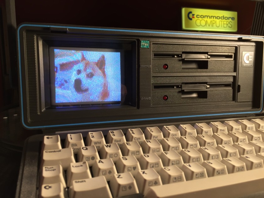
Many floppy. Very retro. Such storage. Wow. #doge #c64
The SX-64 was Commodore’s portable version of the best selling C64 computer that wrapped the C64, a 5″ color display and a 1541 floppy drive into one case that loosely resembled a Kaypro. They were also called luggables because, well, they are quite heavy. Despite folks calling them rare, they litter eBay very frequently and command a premium price.

There was an elusive version created that had two 1541 floppies inside called the DX-64. The second floppy drive replaced the storage glove box of the SX-64. There are some small blurry cam photos of them scattered about and one even popped up on eBay in Oct 2015 and sold for $1,400 but there hasn’t been definitive photos of the exterior and interior of the machine. There’s some questions surrounding the implementation of the second floppy. First, were the drives numbered 8 and 9 or where both device 8 and had logical drive numbers 0 and 1 (reminiscent of the CBM 4040/8050 and the like dual disk drives)? Second, how were they driven? In an SX-64, there’s a single 1541 board that can only drive a single floppy drive. Was there a two drive version of this board? If so, where are the schematic documents or even photos of it?
In any case, I set about to convert an SX-64 to a DX-64 system. This has been completed and documented several times online. Steve Gray has done two and has some excellent photos of the process that I’ll link to now and then throughout this document. I hope to fill in the gaps of some of the things I learned as I completed the conversion of my system.
A word of warning
This conversion is a hack. I’ve attempted to make my modification as reversible as possible, but there are some things that are permanently changed. You should also know that your power supply may not have enough power to drive both disks at the same time. As with any hack advice, you assume all responsibility for what you choose to do to your own machine. I recommend reading all available information on the subject several times before you attempt this conversion. Check and double check your work. If something doesn’t seem right, stop!
Getting the parts
Sourcing the parts is a matter of patience and persistence on eBay. A few times a year, you’ll see a flood of SX-64 parts appear for sale. My guess is someone gets a machine that doesn’t work properly, doesn’t want to ship the entire thing because of weight, or figures they can make more money by parting it out piece by piece. There’s no real advice on the recommended price to pay for these parts, so I’ll leave that to your best judgement.
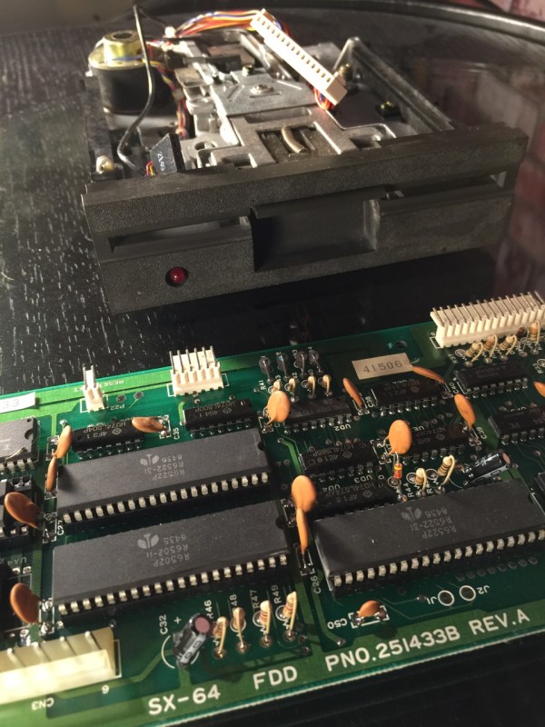
You’ll need the SX-64 1541 controller board called the “FDD” board. I paid $27 (+ $6 ship) for this board. Next is the actual floppy drive itself. There may be other compatible bare floppy drives out there that will work, but keep in mind the latch style, bezel color, mounting holes and wiring loom will need to be right too. I nabbed a SX-64 1541 drive from the same seller for $16 (+ $10 ship). One snag was the seller didn’t have the internal IEC cable that goes from the FDD board to the I/O board. It’s still ok– more on this later.
Testing your new drive and FDD board
Once you have the parts, you should make sure they work 100% before proceeding. This will involve a pretty drastic disassemble of your SX-64. I’m assuming you know how to open your SX-64. If not, please consult Ray Carlsen’s SX-64 guide. And don’t remove the blue handle caps– there’s nothing under there that gains you access to the inside case!
You can leave your old floppy drive in place (rest the new one on top of the storage box) but you will need to remove the original FDD board to get at the power cable on the lower left side of the board (from the rear of the computer). Most everything is held in place by small black plastic posts and rings. Pop these out and set them aside. Unplug the the white 6-pin cable from the original FDD board and plug it into the new FDD board. This is the IEC cable. Plug in the two cable looms from the new drive into your new FDD board as well as the power connector. Double check that you’ve insulated the floppy and the new FDD board from the case. If not, you can count on your machine getting fried. Test the drive thoroughly by loading, saving and even making a copy of a disk or two. Once you confirm the drive works as it should, you can proceed. If not, you’ve got some troubleshooting to do. It’s beyond the scope of this article but consult Commodore sage Ray Carlsen’s site for assistance first.
Change device number to 9
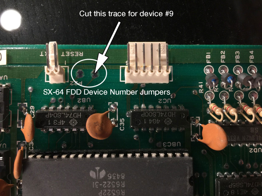
Cut the jumper next to the 6-pin IEC connector for device 9.
Since we’re adding a second drive, we need to change the default device number of the second FDD board from 8 to 9. To do this, locate the two solder jumpers at the top of the board between the reset and IEC pins. Cut the jumper of the pad next to the 6-pin IEC connector as pictured.
Mounting the drive
To install the floppy drive, you first need to remove the storage/floppy “carriage”. On my unit, there’s four vertical screws that secures it to the chassis. On other units, the screws are horizontal which require you to remove the CPU board and the monitor. This sounds like a major pain, but you may be rewarded later.
Lift out the storage/floppy carriage and unscrew the storage box. On Steve Gray’s second conversion, he noticed that his storage box was held into place by small brackets that could be flipped around to hold a second floppy perfectly with the existing screws. This may be the bonus of having to remove the CPU board and monitor. I didn’t have this type of bracket so to fit the new floppy in it’s place, I used screws that had a integrated rubber bushing on it from an old SCSI hard drive. How you solve this problem will depend on what kind of storage/floppy carriage you have.
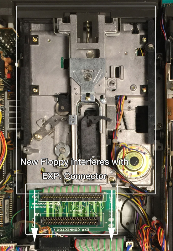
At this point, the cartridge board (or EXP. Connector) is probably in the way, preventing the carriage with the second floppy from being installed. Unfortunately, there’s no room for the cartridge board with the second floppy in place. Here are some alternatives.
- Flip the EXP Connector board 180˚ and screw it into place. This requires all cartridges to be plugged in backwards. I didn’t have enough room inside to do this, as the board would then come into contact with the I/O board connectors.
- Remove the plastic cartridge guide, move the board back and secure with zip ties in the second set of holes. You need a cartridge extender to plug in anything at this point.
- Create a new PCB that is shorter. I did this, more in a later post.
Powering the FDD board
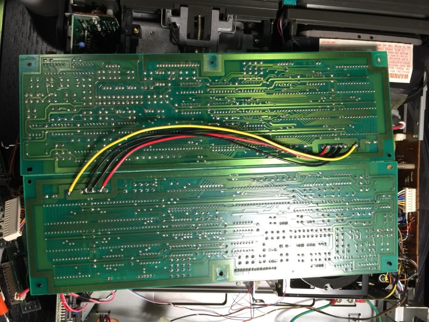
Next, determine how you’ll power the second FDD board. There aren’t any spare power connectors inside so you need an alternative. If you have a spare connector, you could splice it in with the existing one. I didn’t, so I decided to solder the two FDD boards power together from the back. Use a dab of hot glue to secure the cables in place. This allowed the regular power connector to be plugged into one board and have it feed to the second. Use heat shrink/tape to insulate the power connector standoffs on the second card. I went this way because it seemed to be the least destructive of the original hardware. Also, take note that the colors are aren’t the typical colors used for modern power supplies! In this case my YELLOW cable is +5v (it’s ORANGE on my SX-64 power supply cable) and my RED cable is +12v. DOUBLE and TRIPPLE CHECK your work before you power on. You only get one chance.
I had planned to orient the FDD boards back to back (solder side facing inwards) with some heavy insulation between. This didn’t work because it took up too much room. The only way it seems to fit is to have them stacked normally, component sides facing the rear (which is also the original orientation of your original FDD board).
IEC Cable
To connect the FDD boards, you need to make a modified internal IEC cable. This can be accomplished by taking the white IEC cable from your new drive and splicing it into your existing one. Cut both sets of cables in half and splice two ends onto one. Steve Gray did this and has a great picture of it.
If you’re like me and only have one white internal IEC cable, you need to improvise. If you want to make an authentic replacement, the connectors are still available from Molex (PN 51191-0600) as well as the pin inserts. I decided not to go this route because I was impatient (and the crimper tool was expensive for the pin inserts).
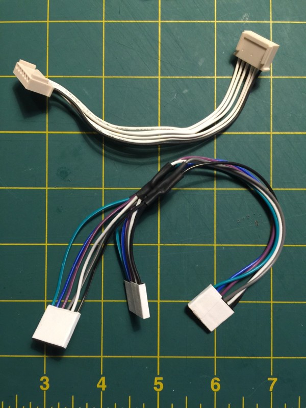
New DX-64 Internal IEC Cable (Bottom)
I did have a stash of female breadboard jumper cables. They just barely fit over the pins. Take 12 female to female jumpers, cut them in half and wire up your own cable like the one shown. Use heat shrink tubing to insulate your splices and use tape to join the individual jumper headers together into 3 single multi-pin connectors.
The pin order appears to be reversed from the I/O board to the FDD board. If the drive doesn’t work, flip it around and try it again.
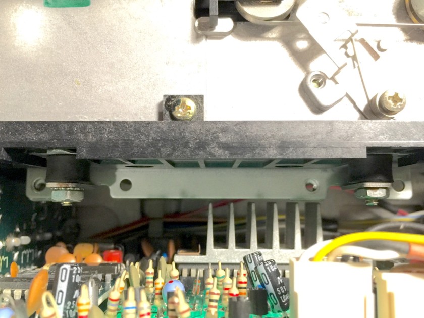
Make room for the FDD board
To make room for the additional FDD board, you need to:
- Remove the post from the right side (closest to the monitor) of the I/O board from the bracket. Remove the metal support bracket by snipping it off at the bottom or simply rocking it back and forth so it bends at the bottom until it breaks off. (pic: Before, After) This part wasn’t detailed anywhere that I could find but there really is no other way to fit everything in with this bracket still in place. Yes, it’s drastic and permanent. If you have a better way, I’d love to hear it.
- Remove the power input socket rear metal shield and shield with thick plastic or paperboard.
- Insulate the solder side of the I/O board and the area surrounding the rear of the monitor.
- Insulate both sides of the FDD boards with thick plastic or paperboard.
- Remove plastic slot/rail on the bottom of the chassis that the FDD board sits in.
Fitting the FDD boards inside
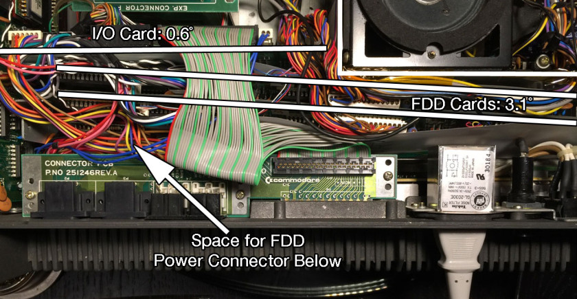
The I/O and FDD boards will be sitting in the chassis at angles. The actual angles aren’t important, but I wanted you to see a diagram of it so you don’t second guess yourself when the boards aren’t sitting at 90˚ angles with the chassis. Stuff the two FDD boards inside the case, making sure that you insulate between all the components very well. It’s all a very tight fit. Attach one FDD board to the right support with the small black plastic pins. The likelihood of anything moving is small because there’s no room to move! Reattach the power supply to confirm that it all fits.
Finishing Touches
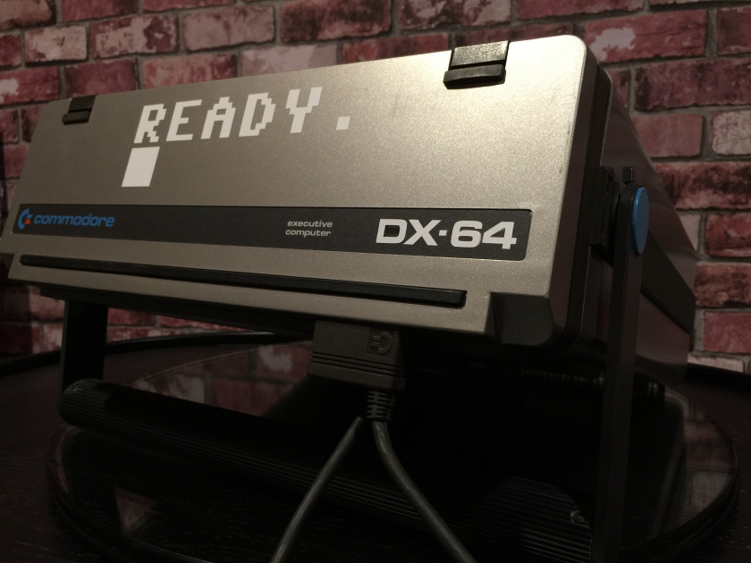
To complete the conversion, the label on the back of the keyboard should say DX-64. I used a vinyl cutter to make an “S” from matte black vinyl and covered just the “S”. Next, I used glossy white and cut “DX-64” and applied it over top the original logo. The look is nearly perfect. The big “READY.” sticker also doesn’t hurt!
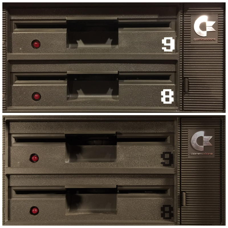
On the real DX-64, the word “storage” on the front bezel is (might be?) replaced with “drive 1.” That would be difficult to change but we can apply stickers to the front of the drive to differentiate them. Here’s 8 and 9 in the Commodore 64 font in black and white. Which do you prefer?
One could also change the startup screen from SX-64 to DX-64 by changing the kernal ROM.
I hope to have an update to the cartridge “EXP. Connector” board mounting problem in a few days.
Adding A Second Drive To A Forgotten Commodore | Hackaday
December 14, 2015 at 1:01am[…] Commodore would never release a laptop, or really much of anything resembling the chunky luggable portable computers of the 1980s. This doesn’t mean a ‘Commodore LCD’ wasn’t designed – it’s sitting in [Bil Herd]’s basement. Of the entire Commodore lineup, the only computer that could remotely be called ‘portable’ is the SX-64, the ‘executive’ version that came with a built-in 5″ monitor, the usual C64 circuitry, one floppy drive, and an empty hole that could obviously hold a second floppy drive. Something must be done about that missing floppy drive, and it only took thirty years for someone to do something about it. […]
Adding A Second Drive To A Forgotten Commodore | KnowNaija
December 14, 2015 at 1:08am[…] Commodore would never release a laptop, or really much of anything resembling the chunky luggable portable computers of the 1980s. This doesn’t mean a ‘Commodore LCD’ wasn’t designed – it’s sitting in [Bil Herd]’s basement. Of the entire Commodore lineup, the only computer that could remotely be called ‘portable’ is the SX-64, the ‘executive’ version that came with a built-in 5″ monitor, the usual C64 circuitry, one floppy drive, and an empty hole that could obviously hold a second floppy drive. Something must be done about that missing floppy drive, and it only took thirty years for someone to do something about it. […]
Sjaak
December 14, 2015 at 4:04amNice to see someone else modding his sx64. Personallyt I would add a SD2IEC drive as second one, but this one looks more genuine 🙂
Any progress on the exp. board? I’m facing the same problem (however for an other cause). I’m planning to make a PCB and get a couple produced.
paulrickards
December 14, 2015 at 6:46pmYes, I got the expansion board but made a mistake. There’s a second revision coming in a week or so that should fix that. I’ll follow up with another post about it.
paulrickards
December 19, 2015 at 5:08pmThe short expansion board PCB has been completed. Take a look at it at this post. Cheers!
Kenneth Dyke
October 20, 2019 at 3:35pmWould you be willing to share your KiCad design files for this? I’m sure I can do my own, but this would save me a bit of time. I have a “DX-64” that I picked up at the Commodore warehouse fire sale back in 1994 when I worked there, and thought it’d be neat to maybe get the expansion port working on it. I also have enough other spare SX-64s to possibly attempt another DX-64 upgrade. (One dead PS, not sure if I’ll be able to fix it yet or not).
GeoAnas
December 18, 2015 at 12:03amAwesome job ! Thanks for sharing.
» SX-64 Short Expansion Board
December 19, 2015 at 5:04pm[…] you were following along with my previous post about converting an SX-64 to a DX-64 by adding a second floppy drive, you’ll know that the process isn’t without it’s problems. There are some […]
Mark Gardner
February 2, 2016 at 2:48pmI don’t suppose there’s any way to do this with an SX-64 and a stock 1541 drive rather than a 1541 and FDD board from a donor SX-64, is there?
paulrickards
February 3, 2016 at 7:21pmUnfortunately, no. A stock 1541’s board is too big. The 1541 board is 6 inches wide while the SX-64 board is 4.5 inches wide. I’m not certain about the drive mechanism itself– that may fit if you get the “push in” door latch type, assuming the cable loom is the same.
I read an idea of using a 1541-II motherboard but I’m not certain of the dimensions or if it has the correct connections on the board to drive a different mechanism.
Peter Lamont
March 14, 2017 at 7:48amI’ll just hook up an external 1541. This is a cool project, but frankly I find the disk storage compartment to be more useful than a second drive believe it or not!
What I would like to have on the SX-64 is a tape drive connector. I bet one could be made to work from the user port if need be…
Wayne Masek
May 13, 2017 at 9:09pmReally enjoyed this process. It is very well introduced with plenty of caution and short cuts without compromising conversion.
Please add me to all future correspondence. I like reading about other conversion projects.
Greg T.
June 22, 2017 at 5:42pmThis is a really neat idea, and it’s awesome it worked out.
I only wish that there was a way to compact a tape drive into that storage slot rather than a secondary floppy bay.
Commodore SX-64 | ancientelectronics
August 7, 2018 at 2:50pm[…] the years but they seem to be exceptionally rare. I’ve read some SX-64 owners have indeed added a second drive in the “storage area” so it can be done. Usually this little storage bay is used to […]
Robert kerans
June 27, 2020 at 12:08pmMany years ago at a computer show in Chicago area, I saw a modified SX 64 where they added a 20 meg Seagate hard drive. I never heard anymore about it or who the company was that did it
Tom Stock
December 18, 2022 at 12:27amToo bad drive 9 is called “Storage”
paulrickards
December 18, 2022 at 10:57amIt’s not wrong though– it’s still storage.