If you were following along with my previous post about converting an SX-64 to a DX-64 by adding a second floppy drive, you’ll know that the process isn’t without it’s problems. There are some irreversible changes that need to be made to the case to accommodate all the extra equipment.
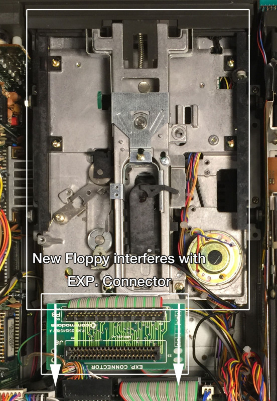
In addition, there’s no room for the cartridge board, also referred to as the “Exp. Connector PCB”. The second floppy drive leaves no room for the original board to rest in it’s original location.
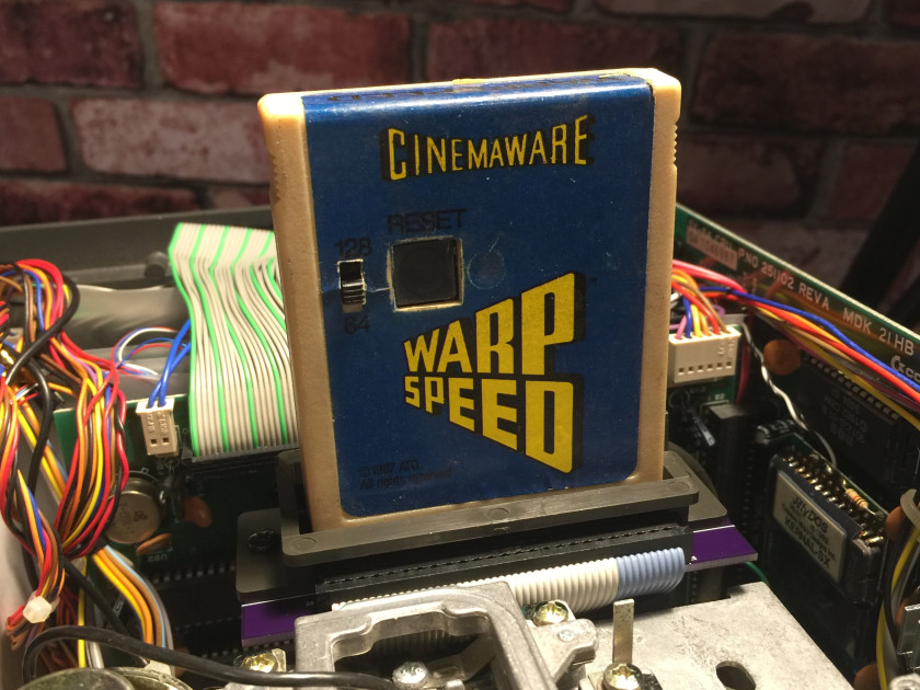
Some have been able to work around this problem by flipping the board around 180 degrees. This can be problematic since now all cartridges need to be plugged in backwards. While that may work for some, I think it could lead to me forgetting and plugging in something the wrong way. I’d hate to damage a 1541 Ultimate II cartridge this way.
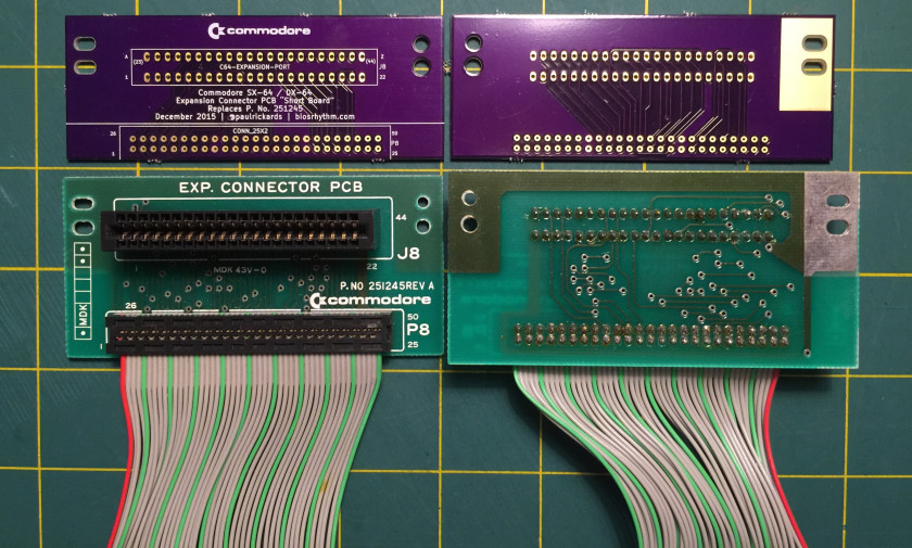
Since the location of the cartridge slot is so critical due to the spring-loaded door opening on the top case, I decided to create a new expansion board that was shorter. The original board is 1.75″ tall. My new board needs to be no larger than 1.4″ tall.
I’ve been learning my way through KiCad creating some cartridges for the Timex Sinclair 2068 and the Commodore 64 so this project seemed easy enough. The board is basically just a passive connector between a cartridge edge and a ribbon cable. The hardest part was measuring everything to ensure I had everything lined up just right. I even created the two parts from scratch, laying out the pins and pitch between them.
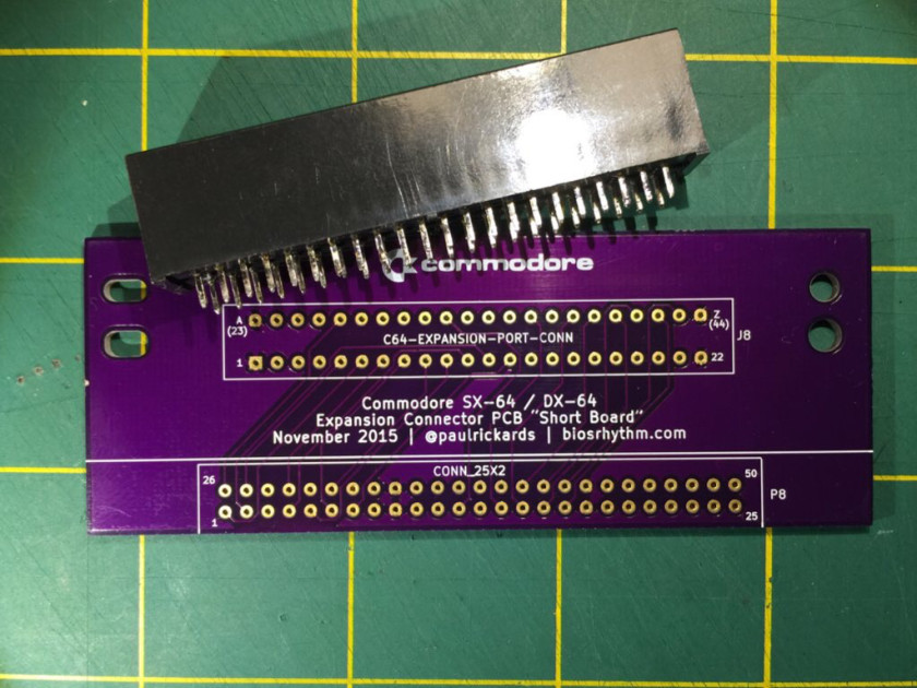
My first revision of the board came back from Oshpark and it looked great. I immediately fire up the soldering iron only to discover I’ve made a mistake– 44 of them to be exact. I didn’t make the holes large enough for the pins of the cartridge edge connector. Bummed, I returned to KidCad to fix my mistake and submitted a second revision and the pins fit as they should.
The next step is to make the ribbon cable. You’ll need these parts.
- IDC 50 pin female dual row header .1″ spacing, $2.83/ea
- IDC 50 pin through hole plug dual row .1″ spacing, $3.04/ea
- 8 inches of 50 position ribbon cable (a SCSI cable or a couple of old IDE cables will work great)
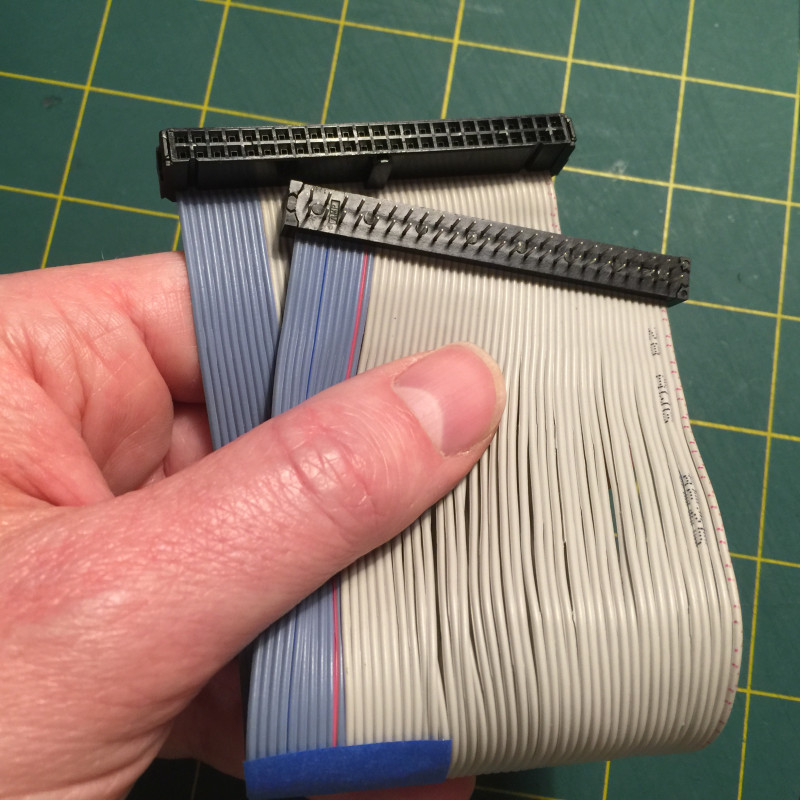
Crimp the connectors on the ribbon cable, matching the orientation of the original cable. I find an easy way to crimp IDC connectors is to use a bench vice. Lightly press the connectors together with the ribbon cable in place, plug them into one another and sandwich it in the vice using an old magazine to protect the connectors from the metal on the vice. Close the vice until the pins are no longer visible.
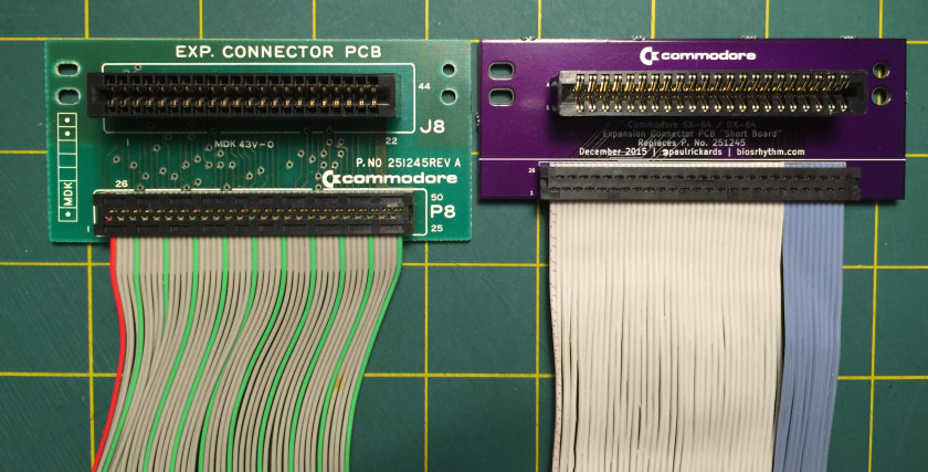
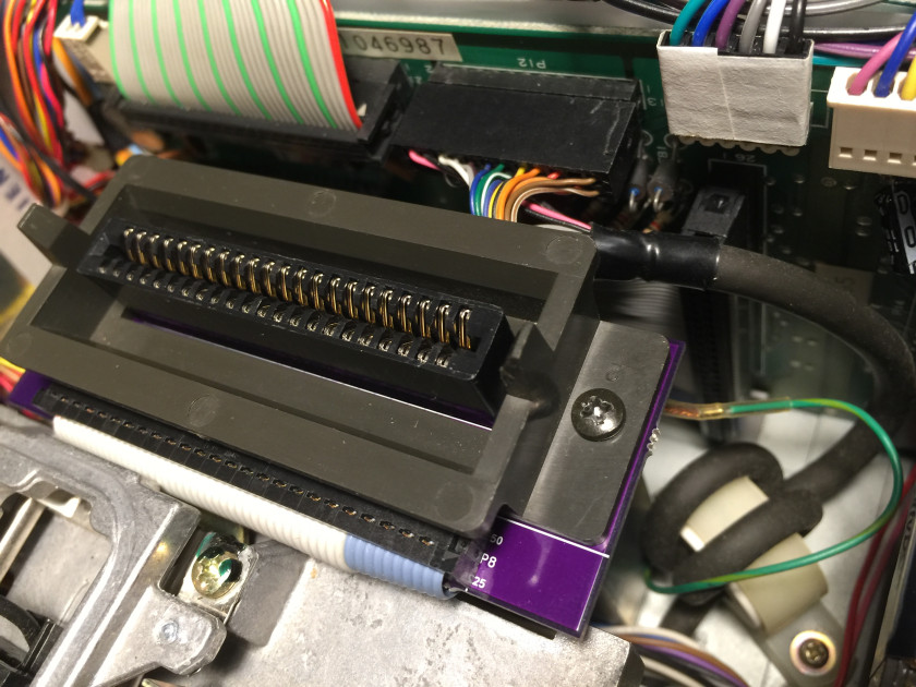
Solder the edge connector and ribbon cable on and install in your SX-64. The clearance is still tight, but should now fit.