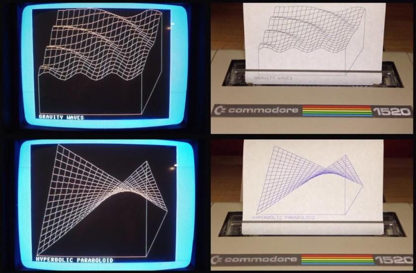
Recently on the Lemon64 forum, user Rizthomas posted some excellent scans of some plots that he did on a Commodore 1520 Printer/Plotter back in 1986. The plots were well executed and very intricate. Some were 2D “string art” and some were 3D functional models. Unfortunately, Rizthomas was unable to locate the original disks for his plots (still hopeful they’ll turn up!) but was generous enough to point everyone in the direction of where he began.
One route was Transactor Magazine Volume 6, Issue 4 which contained a program called The Projector by Ian Adam of Vancouver, B.C. The program was of combination BASIC that built on top of a series of machine language routines (from Transactor Volume 5, Issue 6) that made it easy to draw lines, circles, and text on a hires screen. The routines were called with a SYS command from BASIC and were passed coordinates as variables. This made it incredibly easy to patch the program to also send those coordinates to the Commodore 1520 Printer/Plotter with a few modifications.
- The hires screen coordinates (320×200) doesn’t match the 1520 plotter (480,999) but that’s easily taken care of by scaling the coordinates by a factor of 1.5.
- The program includes several functions to plot contained in REM statements. I broke those out into a menu system so you can choose a function to plot.
- I eventually matched Rizthomas’ color choices by making horizontal lines blue, vertical lines green, bounding box green and text black (on the plot only).
- The origin of the plotter (current pen location at start) is (0,0). Below that point is the negative Y axis so you need to advance the paper up by 300 and then send the “I” command which sets a new “relative origin” point. Now the coordinate systems match screen coordinates (bottom left is (0,0)). Sending the command “R” instead of “M” for moving (pen up) will now use the new relative origin as does “J” instead of “D” for drawing (pen down). The 1520 manual is a great resource to understand the coordinate system of the plotter.
You can download the program (and required ML program) here.
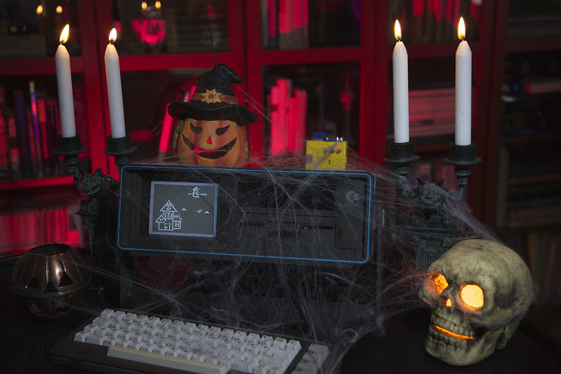
The nice thing about the program is that it will draw a line on the screen while drawing it on the printer simultaneously so you can see both evolve together. Enjoy and a big thanks to Rizthomas for the pointers to the code! If you’re able to get it working, let me know in the comments (and let’s see what you plotted).
Here’s a quick Vine of the plotter working:
 If you use your Raspberry Pi without a keyboard and monitor, you know how frustrating it can be to use it without knowing it’s IP address. By default, the Raspberry Pi is configured to use DHCP to obtain an IP address. This is great for moving the unit around to different networks but can be annoying when you want SSH to the unit. Typically you can use the zero-config/Bonjour “raspberrypi.local” address but this doesn’t always work. I’ve instead come up with a way to use Prowl to notify me of the current IP address after it boots. As a bonus it works with either an Ethernet or WiFi (or both) connection.
 It’s a question that pops up from time to time on forums from