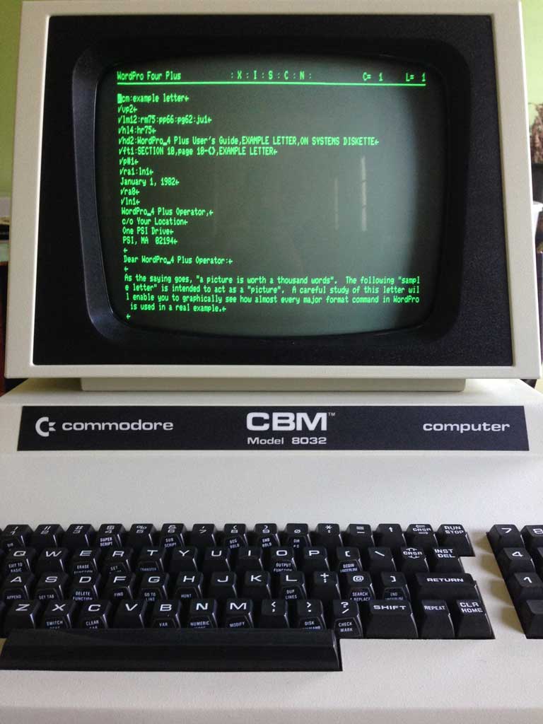
I’ve owned a Commodore PET* 8032 for a few years now. I’ve been able to download and run many different programs for it, like WordPro you see above. But one thing always remained elusive. I’ve long wanted to connect it to a standard RS-232 device and use it as a terminal. The PET’s classic shape, green monochrome monitor, and 80 column display all lend itself perfectly as a terminal.
Like it’s much more popular successors, it too lacked proper RS-232 UART hardware. Adding a modem meant you either had to purchase a IEEE-488 enabled modem (Commodore made the 8010), purchase an add-on board for your PET, or use the existing parallel user port to “bit-bang” RS-232 serial signals. The later is exactly what the Commodore VIC-20, C64 and C128 do– simulate RS-232 on user port pins by the CPU rapidly turning outputs on and off. They even have KERNAL ROM code (albeit broken at high speeds) that did the RS-232 handling for you.
The PET lacks this ROM code but it can added to drive RS-232 TTL signals over the user port. I found two methods that did this– a commercial product and a freeware one.
Before we continue, please– if you attempt any of this, make sure you understand the difference between RS-232 TTL level signals (0v to +5v) and proper RS-232 level signals (-13v to +13v or more). Connecting proper RS-232 level signals to your PET will damage your computer and make you sad. See this explanation for SparkFun about the differences in RS-232 levels.
The first was McTerm which was produced by Madison Computer. I knew of this company since I owned their McPen lightpen system for the VIC-20 and C64 but I didn’t know their pedigree went that far back. It was sold as three parts– software on floppy, a ROM chip that had to be installed inside the PET, and a user port cable that connected to the RS-232 device. I located the software and the ROM online [local cached copy] but I’ve never actually seen the user port cable before so this was going to be challenging.
The first step was to create the ROM using an EPROM. On the PET 8032, the ROM slot is UD12 which maps to memory location $9000. The ROM code was only 2 Kbytes but I only had 4 Kbyte EPROMs. That’s OK, I just filled the other half with 0xFF. The next problem was the PET ROM slot expected a 2532 style pinout but my EPROM was a 2732 which has a slightly different pinout. Luckily, this can be overcome by making an adapter carrier to swap the 3 of the pins around. This site was useful in creating the adapter so I won’t go into that here. (Note: There’s two adapters on that site, make sure you’re building the 2732 -> 2532.)
Next was the software, which was easy enough to transfer to a 1541 floppy disk that can be read with the IEEE-488 enabled Commodore 2031 Single Floppy Disk drive. I put it as the first item on the disk so the “shift-run/stop” trick will load and run the first item on the disk.
Finally, I needed to figure out how to make the cable. I was going to need to test the user port pins to locate which ones the program was using. I examined how the VIC-20 and C64 do RS-232 over the serial port first. Immediately, I found that pins B and C were tied together for receive (RX). Pin C is PA0 which is a GPIO pin and B is /FLAG2 which I believe is for an interrupt. This makes sense since you want to immediately begin processing incoming data as soon as possible. The PET user port pin B is CA1 is is also for an interrupt. I had a hunch it may be used the same way.
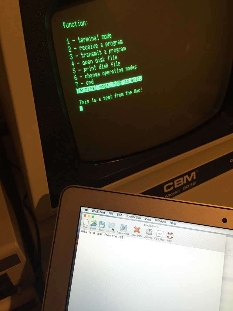
To test the pins, I tied pins B and C together and connected to a USB RS-232 TTL adapter. I used a terminal program called CoolTerm, set the baud rate properly and tried sending characters. Nothing. I then tried B and D. Nothing. I kept trying until I landed on B and F. This DID give me something on the PET screen. It wasn’t correct, but it was receiving something.
I repeated this hunting for the transmit (TX) pin but this time only on a single pin. I found pin H was being using for transmit but again, it wasn’t recognizable characters from the PET but something was being transmitted.
Next I wanted to troubleshoot the characters not being displayed right. First thing was maybe it was the wrong number of data or stop bits or even parity. I tried many different combinations: 7n1, 7e1, 8e2, etc. None of them seemed to make a different. Typing the alphabet “abcdef..” seemed to return the alphabet but in seemingly reverse order with some other characters interspersed.
I decided to get the scope out and look at the differences between the USB RS-232 and PET signals. I decided on the ‘0’ character since it’s the same for ASCII and PETSCII just in case that might be part of the problem. Below is a comparison of the two.
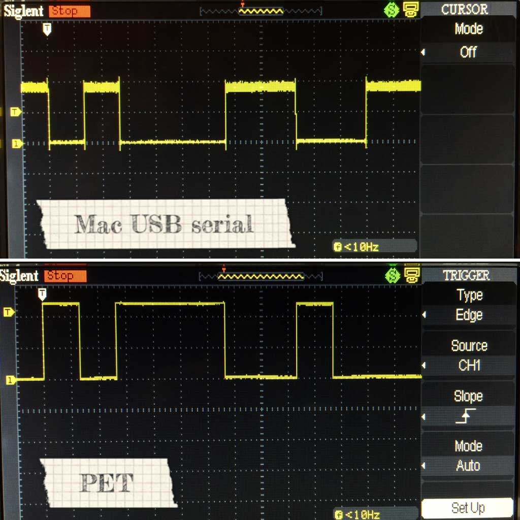
Immediately you can see the issue. The Commodore PET is using a logic low for false and logic high for true (which I’ve learned is called “non-inverse”). Standard RS-232 TTL signals are “inverse” of this using logic high for false and logic low for true. This would explain what I’m seeing since the bits are reversed. I connected the pins through a 7404 inverting IC to invert the singals to and from the PET.
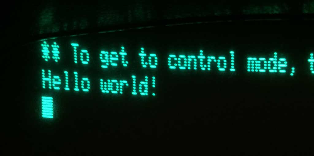
This yielded partial success. I was now able to send characters to the Commodore PET.
Sending characters from the PET to the USB RS-232 TTL adapter revealed that it was setting bit 7 high. If bit 7 was set low, it would be working fine. I’ve still yet to figure this out. If you have an idea, leave a message in the comments.
I later found in the BASIC code of McTerm on line 1070 was a way to use inverted RS-232 which does work without the inverting circuit.
1070 sysa :rem ***** use a for regular modems, a+36 to invert
The second method was found in Transactor Magazine issue 3 volume 6. It included a type in terminal program (simply called “Terminal v11”) and simple instructions for building a user port cable. I believe this program was created by Steve Punter, who also created the only known BBS program for the Commodore PET. Being a type-in freebie in a magazine, it wasn’t as full featured as McTerm but it does do automatic PETSCII/ASCII translation and has file transfers using an early version of the Punter protocol. It is locked to 300 baud however.
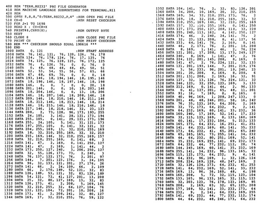
Next up was the software. I really didn’t relish the idea of reliving that part of my childhood and typing all of those DATA statements. Modern technology to the rescue in the form of a free online OCR service. Much to my surprise, this service worked extremely well. I did have to process each column of code separately by extracting each from the PDF as a JPG. The most OCR errors were in the BASIC program but it was still dramatically lower than what I expected. Between the two ML programs with the DATA statements, those only had a single error! I later found version 12 of Terminal was available here [local cached copy].
This time, the PET user port pins were listed. Pins B and L are for RX and pin C is for TX. I swapped my user port adapter cable around to match this pinout, ran the signals through the inverter circuit and tried it. Immediate success in both directions!
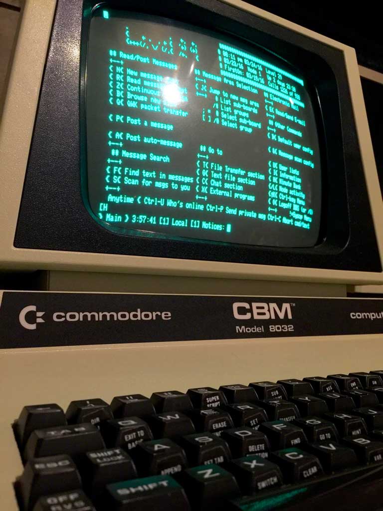
Now that I have a working RS-232 cable and software for the PET, we can put it to use. I connected it to a SparkFun ESP8266 breakout board. This board connects over WiFi and can support a standard Hayes modem AT command set with the right firmware.

With this adapter, I’m able to “dial” into BBS systems that are accessible via IP. One such board is Level 29 which is run by @FozzTexx.
ATDT bbs.fozztexx.com:23
So, was non-inverted RS-232 TTL a standard 30 years ago since two separate terminal programs used it? When did inverted RS-232 TTL become the standard?
So, until I can figure out what’s wrong with McTerm transmitting with bit 7 set, use Terminal instead and you can use RS-232 on your PET.
*Actually, Commodore dropped the PET moniker shortly after they introduced the line and changed it to just CBM. The name PET just fits better I think.
Christian Vogel
March 28, 2016 at 3:53amI think your scope traces don’t show a ‘0’ (number Zero, ASCII code 0x30 or $30 as commonly written in the days) but rather…
{ Start=0 LSB=1 000110 MSB=0 Stop=1 }
…which is 0x31 = ‘1’. As for why would you wasn’t to invert the data line? RS232 normally is -12V..-5V for a ‘1’ on the data line and +5V..+12V for ‘0’ on the data line. But the threshold to distinguish between the two states, in most equipment was slightly positive. So 0V was detected as a RS232 ‘1’. Making use of this undefined behaviour of a modems RS232 receiver, you didn’t need to translate from TTL to RS232 but just connect with a straight wire. In the other direction, modem to comouter, you’d use clamping diodes and a resistor.
DrDiesel
June 14, 2016 at 7:54amGreat article! Funnily enough I’m in the middle of reverse engineering the original Madison RS232 adapter and found the same user port pins being used. It actually uses another user port pin, pin L, which is connected to DCD, the carrier detect (pin 1 on the 9pin RS232 connector). This allows the software to detect when a remote modem has made a connection.
As for the bit-7 problem, it may have something to do with ASCII vs PETSCII. There is a option in McTerm to change the type of communication, i.e. “PET to ASCII” or “PET to PET”. Might be worth a try.
Cheers!
paulrickards
June 14, 2016 at 10:40amWow, great to know that someone else is working on mapping the Madison RS232 adapter. There’s not a lot of info about it out there.
Thanks for the info on the additional pin for carrier detect. Do you know if it does anything in the software other than toggling something on screen?
I think I did try the PET/ASCII and PET/PET switch but don’t think it made a difference. I’ll have to give it another try.
Which version of the ROM are you using?
Cheers!
Dr Diesel
June 15, 2016 at 3:56pmI’m not sure how the software reacts to carrier detect, but the idea is that the software will give an error message when the connection has been lost (if the modem supports that function that is).
I think all the ROM versions are the same, only the software comes in different versions. I’m using V1.26C.
I’m currently in the process of veroboarding a prototype interface, but using a MAX232 to give proper RS232 levels. That way I can connect real serial port hardware. Will let you know how I get on!
paulrickards
June 15, 2016 at 7:27pmI know of two ROM revisions for MC Term: v1.17 and v1.21. The BASIC software revisions seem to have a wide range of ROM versions they’ll support. For instance. V1.26C supports the v1.21 ROM.
Keep us posted– it’ll be great to have a proper RS-232 cable for the PET again.
DrDiesel
June 27, 2016 at 7:29pmThat’s interesting! Must check to see what ROM version I have.
Have finished building my adapter, seems to work OK except for the problems you have already highlighted. Changing line 1070 takes care of the inverter problem, so no actual hardware inverter is required. Very simple circuit in the end.
The Bit-7 problem seems to stem from the fact that original ASCII is 7bit, so the value of the 8th bit shouldn’t matter, however modern terminal software often uses 8bit codes to give you more characters. I’m using HyperTerminal on Windows and there is an option to force 7bit ASCII on the input string, so the fact that McTerm sets the 8th bit doesn’t matter. Communication in both directions works flawlessly that way (as long as the PET-to-ASCII option in McTerm is set). I haven’t tried any BBS’s with McTerm yet, so I don’t know if they interpret the 8th bit or not.
Siri Like it’s 1976 With a TI Silent 700 Terminal – Cameron Coward
August 8, 2017 at 6:39pm[…] so I thought. That’s when I was doing research for Hackaday (where I write), and came across this great biosrhythm article RS-232 (serial) on a Commodore PET. It seemed like a fun project, so I was happily reading along when I came across this […]
Andrew Faull
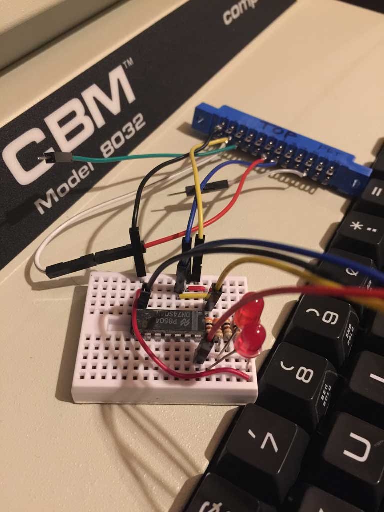
November 2, 2017 at 1:25amSo I see there are also a few resistors next to the inverter. What are those doing? I am going to have to try to make a copy of your breadboard project. I have two 8032’s and an old 2001.
paulrickards
November 2, 2017 at 8:57amHi Andrew, The resistors are there for the LEDs which were to a visual way to indicate activity.
Paul Stubbs
November 24, 2017 at 7:36amAs far as I know inverted TTL (as in 5V) was the standard way, becase the standard RS232 driver chips of the day were the 1488 & 1489 chips, these days a popular alternative is the MAX232, and its many clones. All of these devices invert the signal.
UART IC’s of the day assumed inverting drivers, so they standardly output inverted serial 5V, ready for it to be inverted and stepped up to +-12V signals.
G
May 16, 2020 at 7:04pmHi,
What is the maximum baud rate that you can reach using this method?
I am using this: https://github.com/ChartreuseK/PETTERM/releases, and it only supports 300 baud.
Thanks,
G
paulrickards
May 17, 2020 at 8:29amThe limitation of baud rate is on the PET side. PETTERM and “Terminal v11” can only do 300 baud. MCTerm can do 300 or 1200. The WiFi hardware itself can go much faster than the PET can do.
G
May 23, 2020 at 4:45pmThanks for your reply; only just checked back today.