Recently I’ve been repairing a batch of broken Commodore 64’s that I scored on eBay for cheap. Out of the repairs, two boards were beyond hope but still had some usable parts on them so motherboards became donor boards. That left me with a couple empty cases and keyboards so I decided to make a Commodore 64 USB keyboard.

There’s already a nice product called Keyrah that does just this (plus a lot more) and I recommend you checking it out as it adds Amiga keyboard and joystick support.
But if you’re like me and want the challenge, I decided to go the maker route.
First, I searched for any such projects– no sense in re-inventing the wheel. I found a project by Mikkel Holm Olsen called C64 USB Keyboard. It used an Atmel ATMega-8 chip which I’ve learned is very similar to Arduino’s 168/328P chip. It might work but with some modifications– beyond my skill set today. I shelved this project and continued.
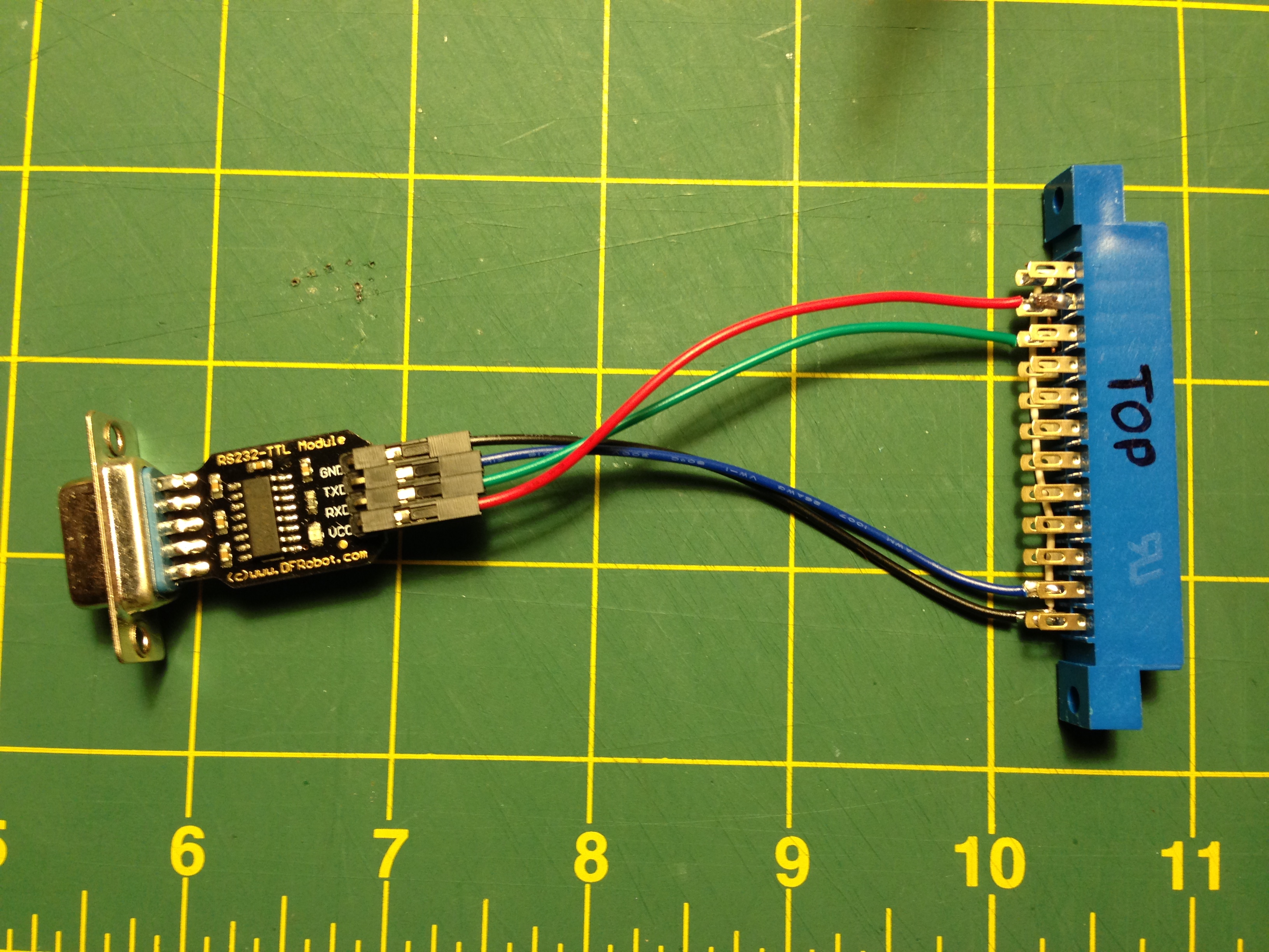
The keyboard is basically an 8×8 matrix keypad. There’s already a keypad library for Arduino. A couple of things that I discovered while using this library. One, don’t use pin 13 with the C64 keyboard. It’s probably because of the built in resister and LED that causes the pull ups to not work. An outside pull up might fix this. Two, the library only supports single keypresses. This is a bummer since you often will press two keys (i.e. the shift key, control, etc). But I worked around it. I put together a quick harness that will connect the Commodore 64 keyboard to the Arduino, aligning the rows and columns to the right pins. I like to make my projects the least destructive way so I use a lot of tape, jumpers and breadboards.

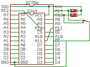
Getting the Arduino to talk USB makes use of the V-USB library which has been ported to Arduino. I really like this implementation because it’s all handled by the Arduino and needs very little passive glue on the outside to make it work. Below is a diagram of how to hook up USB to the Arduino. The values on the diodes are pretty strict and must be 3.6V 500mW zener diodes (although I hear 250mW is better). More information can be found in the V-USB documentation.

I made a small change to the V-USB code and moved the USB data (-) from Arduino pin 4 to pin 3– just edit usbconfig.h inside the UsbKeyboard library. I also commented out the optional connect/disconnect on pin 5 because I simply don’t have the pins to spare! Connected, the inside looks like this.


The pin mapping goes like this:
C64 Pin Arduino Pin
Column 0 = 13 -> 4
Column 1 = 19 -> 5
Column 2 = 18 -> 6
Column 3 = 17 -> 7
Column 4 = 16 -> 8
Column 5 = 15 -> 9
Column 6 = 14 -> 10
Column 7 = 20 -> 11
Row 0 = 12 -> 12
Row 1 = 11 -> 0 (This was pin 13 if you’re wondering why the break in continuity)
Row 2 = 10 -> 14 (Analog 0)
Row 3 = 5 -> 15 (Analog 1)
Row 4 = 8 -> 16 (Analog 2)
Row 5 = 7 -> 17 (Analog 3)
Row 6 = 6 -> 18 (Analog 4)
Row 7 = 9 -> 19 (Analog 5)
I power the Arduino via the incoming USB. To get it to be recognized properly by your computer, unplug the USB programming cable from the Arduino and then plug in the USB cable to the V-USB side. Otherwise it will not be recognized. It makes for a lot of cable swapping unfortunately while coding. I also powered the C64 power LED for nostalgia (this may be a good use for pin 13).
Speaking of code, I needed to define some key codes that were missing from the UsbKeyboard library. This was fairly straight-forward by looking them up on the USB HID guide (chapter 10). I also defined “bogus” key codes that I could intercept and do something else with. Most keys on the keyboard can be passed straight through. Others, like the arrow keys, F-keys, quote, asterisk, etc need a little more help since their locations are different than a standard keyboard. I also hacked together to ability to detect a modifier key (shift, control, etc) along with another key (from the keypad library). The resulting code isn’t pretty but I think it’s easy enough to follow. It’s included below for your amusement.
This project is far from perfect but it’s a start.
#include <Keypad.h>
#include <UsbKeyboard.h>

// Define keys that are missing from UsbKeyboard.h
#define KEY_ESCAPE  41
#define KEY_DELETE 42
#define KEY_TAB 43
#define KEY_MINUS 45
#define KEY_EQUAL   46
#define KEY_LEFTBRACKET 47
#define KEY_RIGHTBRACKET 48
#define KEY_BACKSLASH 49
#define KEY_SEMICOLON 51
#define KEY_SINGLE_QUOTE 52
#define KEY_BACKTICK 53
#define KEY_COMMA   54
#define KEY_PERIOD  55
#define KEY_SLASH   56
#define KEY_INSERT  73
#define KEY_HOME    74
#define KEY_PAGEUP 75
#define KEY_PAGEDOWN 78
#define KEY_RIGHTARROW 79
#define KEY_LEFTARROW 80
#define KEY_DOWNARROW 81
#define KEY_UPARROW 82
#define KEY_AT      206

// Bogus key codes, intercepted in code below
#define KEY_PLUS 249
#define LEFT_SHIFT 250
#define RIGHT_SHIFT 251
#define COMMODORE 252
#define CONTROL 253
#define KEY_COLON 254
#define KEY_STAR 255

const byte ROWS = 8;
const byte COLS = 8;
byte mod = 0;

// Define the Keymap
char keys[ROWS][COLS] = {
 {KEY_DELETE, KEY_ENTER, KEY_RIGHTARROW, KEY_F7, KEY_F1, KEY_F3, KEY_F5, KEY_DOWNARROW},
 {KEY_3, KEY_W, KEY_A, KEY_4, KEY_Z, KEY_S, KEY_E, LEFT_SHIFT},
 {KEY_5, KEY_R, KEY_D, KEY_6, KEY_C, KEY_F, KEY_T, KEY_X},
 {KEY_7, KEY_Y, KEY_G, KEY_8, KEY_B, KEY_H, KEY_U, KEY_V},
 {KEY_9, KEY_I, KEY_J, KEY_0, KEY_M, KEY_K, KEY_O, KEY_N},
 {KEY_PLUS, KEY_P, KEY_L, KEY_MINUS, KEY_PERIOD, KEY_COLON, KEY_TAB, KEY_COMMA},
 {KEY_PAGEDOWN, KEY_STAR, KEY_SEMICOLON, KEY_HOME, RIGHT_SHIFT, KEY_EQUAL, KEY_BACKSLASH, KEY_SLASH},
 {KEY_1, KEY_BACKTICK, CONTROL, KEY_2, KEY_SPACE, COMMODORE, KEY_Q, KEY_ESCAPE}
};
byte colPins[COLS] = {4,5,6,7,8,9,10,11};
byte rowPins[ROWS] = {12,0,14,15,16,17,18,19};

// Create the Keypad
Keypad kpd = Keypad( makeKeymap(keys), rowPins, colPins, ROWS, COLS );

void setup()
{
}

void loop()
{
  UsbKeyboard.update();
  mod = 0;

  // Kludge, find activate modifiers
  // control   [7][2]
  // commodore [7][5]
  pinMode(rowPins[7], OUTPUT);
  digitalWrite(rowPins[7], LOW);
  if (digitalRead(colPins[2]) == LOW) { mod = mod | MOD_CONTROL_LEFT; }
  if (digitalRead(colPins[5]) == LOW) { mod = mod | MOD_ALT_LEFT; }
  pinMode(rowPins[7], INPUT);
  digitalWrite(rowPins[7], HIGH);

  // left shift[1][7]
  pinMode(rowPins[1], OUTPUT);
  digitalWrite(rowPins[1], LOW);
  if (digitalRead(colPins[7]) == LOW) { mod = mod | MOD_SHIFT_LEFT; }
  pinMode(rowPins[1], INPUT);
  digitalWrite(rowPins[1], HIGH);

  // right shift[6][4]
  pinMode(rowPins[6], OUTPUT);
  digitalWrite(rowPins[6], LOW);
  if (digitalRead(colPins[4]) == LOW) { mod = mod | MOD_SHIFT_RIGHT; }
  pinMode(rowPins[6], INPUT);
  digitalWrite(rowPins[6], HIGH);

  if (mod == 6) {
    UsbKeyboard.sendKeyStroke(0, mod); // This works, but sends 3-4 times. :(
    return;
  }

  char key = kpd.getKey();
  if (key) {
    switch (key) {
      case KEY_STAR:
        UsbKeyboard.sendKeyStroke(KEY_8, MOD_SHIFT_LEFT);
        break;
      case KEY_AT:
        UsbKeyboard.sendKeyStroke(KEY_2, MOD_SHIFT_LEFT);
        break;
      case KEY_PLUS:
        UsbKeyboard.sendKeyStroke(KEY_EQUAL, MOD_SHIFT_LEFT);
        break;
      case KEY_COLON:
        UsbKeyboard.sendKeyStroke(KEY_SEMICOLON, MOD_SHIFT_LEFT);
        break;
      default:
        if (mod == MOD_SHIFT_LEFT || mod == MOD_SHIFT_RIGHT) {
          if (key == KEY_2) { key = KEY_SINGLE_QUOTE; } // "
          if (key == KEY_7) { key = KEY_SINGLE_QUOTE; mod = 0; } // '
          if (key == KEY_6) { key = KEY_7; } // &
          if (key == KEY_9) { key = KEY_0; } // )
          if (key == KEY_8) { key = KEY_9; } // (
          if (key == KEY_DOWNARROW) { key = KEY_UPARROW; mod = 0; }
          if (key == KEY_RIGHTARROW) { key = KEY_LEFTARROW; mod = 0; }
          if (key == KEY_F1) { key = KEY_F2; mod = 0; }
          if (key == KEY_F3) { key = KEY_F4; mod = 0; }
          if (key == KEY_F5) { key = KEY_F6; mod = 0; }
          if (key == KEY_F7) { key = KEY_F8; mod = 0; }
        }
        UsbKeyboard.sendKeyStroke(key, mod);
        break;
    }
  }
}
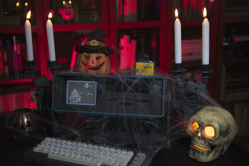
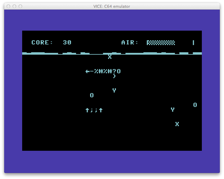 It’s BASIC Week on Reddit/r/RetroBattlestations and I ported the BASIC Week program “Under the Sea” to the Commodore 64. The original code was written by FozzTexx for the IBM PC which allows for variable names longer than two characters. The Commodore 64 BASIC version 2 would probably still work using the longer names, it would just ignore everything after the first two characters. Doing this though would run the risk of overwriting variables so it was best to convert them. You can find a list of the variable name conversions at the end of the post.
 It’s a question that pops up from time to time on forums from
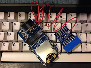


 The Chameleon 64 is a great cartridge. With each release of the firmware, new features are being unlocked. Recently, the Minimig core was ported to the Chameleon 64 which means you can now have a fully emulated Amiga that fits in the palm of your hand.