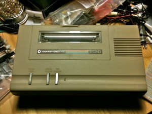
 My first computer was a Commodore VIC-20. I got it as a Christmas present from my parents in 1982. I’m pretty sure they picked it up at Montgomery Ward, which was still around at the time. Shortly there after, I got my first printer to go with it. A Commodore 1520 Printer Plotter.
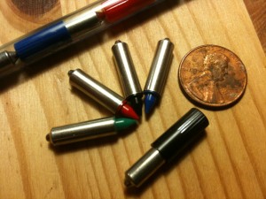 This printer was great. Firstly, it was tiny for a printer. It was smaller than the computer! Everything about it was tiny. It used tiny 4.5″ wide paper that was on a roll. It used tiny ball-point pens (yes, pens!) of four colors that it could selectively choose. I used it well, mostly printing nonsense I’m sure. Time passes and the printer disappears. I think I may have “taken it apart” which for me at that time usually meant destroying it. In any case, the original never followed me.
Fast forward to 2001 when I bought two from eBay. One came with the box and some extra pens (which proved to be the most elusive consumable). But irritatingly, the printer seemed to have fits when it was asked to print something. The motors would make an unpleasant noise and the print head would vibrate in place. The paper advance was also acting up.
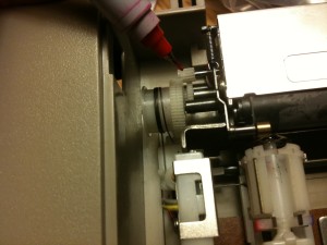 Upon further inspection and some help from the interwebs, I found the culprit. A very tiny gear connects the stepper motor to the rest of the gearing to move both in the X (print head left and right) and Y (paper up and down). These two gears, made of nylon or plastic, have shrunk over time and split, causing the teeth of the gear to get jammed. Commodore sourced the plotter mechanism from ALPS (as did Tandy, Atari and Mattel for their plotters). Likely all plotters using this mechanism are suffering the same fate. Frustrated, I shelved it.
Fast forward to 2009 when I take a course in historical computers, I decided to revisit the printer to see if I can repair it. I found a terrific resource on a Commodore 128 forum from user “airship” he calls The 1520 Plotter Survival Guide written in 2007. It lists sources for the paper, the pens and possible help in fixing the gears.
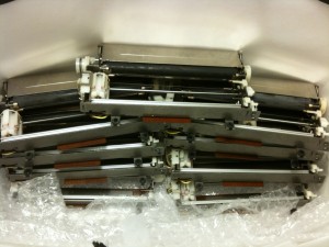 To fix the gear issue, I decide to take the repair route. A company called Electronic Goldmine has the ALPS plotter mechanism (surplus) that Commodore used (at $1.49 ea!). I buy 10, hoping that at least a couple of the gears will be good. All of the gears are split– time has not been good to them. But the good news is the mechanisms make great replacements if the original motors are bad. Plus it gives me 20 gears to try and fix various ways.
To repair the gears, I first remove them from the stepper motor. They’re just pressure fitted so they slide off. I used some super glue to fix the split back together and clamp it together overnight. I then use a 1/16″ drill bit to drill out a tiny amount of the center of the gear. This will relieve the strain and prevent further splitting when the gear is back on the motor shaft. Next, I dry test the gear on the motor and see if it works. If it does, I use super glue to attach the gear to the shaft.
The result:
It works! I keyed in a demo program from the manual and produced this:

Coming up in another post I’ll show you what it looks like when it plots text (with slow motion video).
Conrad
March 14, 2013 at 10:43pmDo you have any spare as working condition for my Commodore Plotter 1520 ? I has 2 of them that show blinking red LED.
admin
March 15, 2013 at 1:38pmI don’t, sorry. You might have good luck buying one from eBay– they tend to appear there on a regular basis.
Gene
June 13, 2014 at 12:23amI just received a 1520, and both the x & y gears are split. I will attempt to fix them. But, when you turn my 1520 on, the X carriage motor runs the pen all the way to the left, then the X or left-most motor clicks by turning on and off rapidly for about 10 seconds, then stops. Then the power light shows an error by flashing at the same time as the motor stops working. Any clues?
paulrickards
June 14, 2014 at 8:21pmHi Gene, When you first power on the 1520, it will go through a self-test and print-test mode. Here’s what it performs:
1. Power on, carriage moves all the way to the left. If it’s there already, it will “grind” away for about 2 seconds.
2. It then will bounce 3 times (left/right) in the left margin to change the pen color until it detects blue.
3. It draws a small box in the current color.
4. It repeats steps 2 – 3 drawing green, red and black boxes.
The flashing is showing an error code, most likely because of the split gears, it’s unable to cycle and find the first color (blue). Repair the gears and you should be good.
Paul
Gene
June 29, 2014 at 6:59amOk, good news!
Not only did I fix my 1520, but I found a source to replace the split gears at a local hobby shop!
The brand is “Losi.” They are a division of Horizon Hobby of Champaign Il, and their phone number is on their website, http://www.losi.com
The part number is LOSB1752 and I paid $7.99
It’s called a “Pinion and spur set: micro sct, rally”. It has several gears enclosed, the smallest fits. You will need to enlarge the hole, I used the smallest round rat tail file from a set sold at Harbor Freight, p/n 00468.
I enlarged the hole so that the gear easily slides onto the motor’s shaft, without being too loose, I then applied epoxy and let it set up.
That’s all there is to it.
They have offices in the UK and Germany, btw.
I .
Dean
September 1, 2014 at 3:55pmI was skeptical about super gluing nylon. (the material that I believe the gear is made of after examining it under a microscope). The key is what you said – use a 1/16 drill bit after gluing to make the bore wider before you put it back on the shaft. If you don’t, it will just split immediately again since the superglue bond is much weaker that the original material. With your fingers you can easily use a 1/16 drill bit to SLOWLY insert and back out as spinning it to bore out the hole after gluing. Don’t jam the drill bit all the way in. Just put it a small amount (slowly) while slowly spinning the drill bit, then back out. Proceed again little forward then backing it out multiple until you are all the way through (hopefully without splitting it). Then dry test as “admin” indicated. If it works ok in the dry test you might then clean out a bit of the material in the gear well where you put the glue to get some of the excess out. Then put on shaft, take note if there is an area where it rotates best without snagging at all so that when you put the (tiny!) amount of superglue on the shaft you can position the gear to the “sweet spot” for smoothest rotation against the opposing gear. Also what I did before applying glue to the shaft was to put the gear on the shaft and slide close to motor. Then put a small(!) amount of glue to the shaft then slide the gear into the sweet spot position. Worked great so far and I have resurrected both gears on one unit. For the second plotter I have I am going to buy the LOSB1752 gears to see how they work too.
Dean
September 1, 2014 at 4:30pmAlso, should have mentioned…before gluing, clean the gears in acetone using a toothbrush to remove any gear lube or anything else that might be on them or in the bore. Also use a Q-tip with a small amount of acetone on it to clean the motor shaft. Don’t use too much on the Q-tip since you don’t want the acetone to get into the motor where the shaft enters.
paulrickards
September 1, 2014 at 4:31pmHi Dean, That’s excellent! I did exactly as you described, I “hand drilled” with a bit to make the bore wider. That makes up for the material shrinking. Very happy that you were able to get your plotter working again. And do let us know how the new LOSB1752 gears work out for you. I’ve yet to try it myself. Cheers!
Dean
September 1, 2014 at 10:48pmI bought the LOSB1752 gear set and was disappointed. Not compatible at all if you want to plot correctly. The smallest gear looked close but it only had 12 teeth versus the 13 teeth on the original. So I just used the glue method to repair my second plotter today (works great!). I needed to actually remove some material from the cracked surfaces to make it so that the pitch was correct when clamped together. Make sure you don’t glue until you confirm under a microscope that when clamped the teeth adjacent to the crack have the same spacing as the other teeth or you will be re-doing it (way more painful once glued…). Another tip, for a clamp, you can use a pair of pliers with rubber bands around the handles. Good luck everyone and thank you to the first poster.
paulrickards
September 2, 2014 at 10:02pmHi Dean, That’s too bad but also an important distinction if the replacement gear doesn’t have the same number of teeth! I also like the idea of rubber banding a pair of pliers to use as a clamp– clever! I ended up using a small caliper set that had a very fine adjustment to clamp it together with just enough force.
Dean
September 4, 2014 at 10:54pmI may have spoken too soon on the LOSB1752 gear kit. I focused on the smallest gear provided in the pack based on the earlier poster’s comments (it actually had 10 teeth, I was wrong in my earlier post but still, it has the wrong number of teeth). However, I went back and looked at the gear set again before getting ready to pitch it in the garbage and I noted that the slightly larger than original gear in the pack had 13 teeth. However the OD looks slightly bigger (I can put calipers on it later) and the pressure angles looks different. Unfortunately I already fixed all 4 of the original printer gears on my two printers so its hard to do a real test since I don’t want to break them again! So if others get a chance to try them please let me know.
Joe
October 5, 2014 at 2:18amThank you for pointing out the problem with the little gears and for showing how to fix them. Without your help, I would have given up. My Radio Shack CGP-115 had good gears, but one failed after printing outside the printing field, which caused enough strain to actually bite off two teeth from the left little gear before it split. I tried a trick I have used before to weld Nylon, in particular, very small parts. I use a very thin wire strand, which in this case was even thinner than my hair and was maybe one third the thickness of the gear crack. I place the fine wire inside the crack lenght wise and clamped the gear with self-grabbing tweezers. Then I applied a few volts to the wire to get about 1Amp of current flowing. It is best to use a 0-10V 1A variable supply. In a few seconds (10s-20s) there was noticeable melting around the very fine wire. The melted zone did not spread much beyond the wire, but I held it hot for some 10s to be sure that enough of the gear crack melted to weld. After cooling, the wire stays embedded and I clipped off the excess wire. Then I used a very fine file to widen the hole as described above. I used a drop of super glue, but positioned the gear such that the intact portion of the teeth would be aligned with the next gear. By the way, At least one set of 30 year old NOS Radio Shack pens that I had saved, was quite good. They were in their original caps, which fit tightly. Perhaps the caps shrunk a little too, thus ensuring a tight seal.
Joe Sousa
October 9, 2014 at 4:15amAfter getting the little plastic gear welded and glued back, I decided to see what I could do with the pens.
I have a set of 4 good NOS pens that survived 30 years in their blister pack with caps on. Before I realized I had a good set of pens, I also bought set of 4 NOS pens from ebay seller dwightspeadlehacker. These were good too. I also have 8 dried up pens and decided to see if I could revive them. In talking with a friend, who was a printer engineer for a number of years, he told me that the ink was most likely water based. So I set about to rehydrate the dried-up pens.
I put the pens in a test tube with water and heated the tube to the boiling point. I could see air bubbles come out of the thin air slit between the plastic tip and the metal body. When the water cooled with the pens in it, the water was sucked right into the pens. I tried this trick on 8 dried pens and was able to revive 5 of them. The plastic tips of the pens did no appear to suffer any ill effect from the boiling hot water.
You can do this more than once, if you still see any air still bubbling out of the pen. When the pen is fully rehydrated, heating it will make ink come out of the air slit.
You might want to boil the water without the pens first, to free it from air. This way, when you boil pens in the water, the only visible bubles come from the pen air slits.
paulrickards
October 10, 2014 at 9:18pmHi Joe, That’s great news and certainly an easy way to attempt to revive dried up pens. I’ll have to give this a try. Thanks!
Brian K. White
February 21, 2015 at 10:00pmI had no success with cyanoacrylate and drilling. The super glue just didn’t stick even a little, and the drill just split the thing open again instead of drilling.
What I DID manage to do was mount a 1/16″ drill bit in a set of forceps, and clamped the forceps in a small table top vice. Such that the forceps are clamped onto the drill bit on the shank right next to the begining of the flutes, and the majority of the smooth shank pointing roughly at myself. The cutter part of the drill bit points away from me and is not touched. This makes a very sturdy mount to hold the shaft, and will allow the shaft to get hot.
Then I put one gear onto the end of the shaft. Then I held a 12 watt (yes 12) soldering pencil to the shaft in between the gear and the forceps, and waited for the gear to soften in the center. The center part starts to go from white to clear, and the split gap closes. I remove the heat and rotate the gear on the shaft feeling the viscous melted center start to harden. The teeth are reasonably safe, just take away the heat after the split gap closes, but leave it on long enought to see the clear melted part spread out from the shaft enough that the split gap looks well and truly welded.
The point of the twirling in my fingers is to keep the gear centered as it hardens. When I first did this without touching the gear much, the gear slumped off center from gravity as it cooled. It sounds, (and looked and felt!) pretty destructive because melted nylon spooges out the end, and you know you are making the bore larger and no longer machine perfect and everything. But it worked !
Then I just slipped the gears back onto the motor shafts with a drop of fast setting loctite super glue. Loctite super glue professional liquid in a hard blue bottle from walmart. It sets instantly, in a second. But weak enough on polished chrome and nylon that you can break it free later if you need to again.
I also had to glue the gear that goes onto the rubber roller shaft. The gear itself needed no repair, it just was slipping on it’s shaft and the paper wasn’t moving up and down as it should. The glue seeps up in between the the two spring tensioned gears, but it’s weak on the nylon so you just slice an xacto knife in between them and they are free again. You are supposed to rotate one gear one tooth offset from the other at rest, compressing a spring inside, as you slide the intermediate gear into place between the motor and platen. This takes up play in the gear teeth so that the printing is as accurate as possible.
Finally a little manual touch up scraping glue out of teeth with an xacto and one of those hobbyist/electronics magnifying glass head hood things, until the imperfections are smoothed out.
End result, It prints clean!
I ordered that losi gear kit and sent an email to losi product support to ask for more detailed help for a 13 tooth, 4mm o.d. pinion gear. So, maybe we will have a way to just get new gears and not have to get so exotic trying to repair them. But at least it worked!
Also I found a manufacturer of new pens in Germany. You can’t order directly from their website in the U.S., but you can email them and pay them by paypal and they send you the pens no problem. They speak English too. Took a couple weeks to arrive but it was an easy email and paypal process. A bit expensive, like almost $30 per set of 4. The color set includes one black. The black set is 4 black. So you can just get one color set and you’re good.
lass-shop dot de , search “stifte”
I got paper from pospaper dot com. 24 150 foot rolls for about $20. Anyone want some paper?
*(12W is less common than 15W, you could use a 15W but I would avoid anything higher. Way too hot.)
Aberto
March 20, 2018 at 6:19pmHi, my 1520 Plotter has the ALPS plotter mechanism brocken: the pens housing doesn’t rotate anymore and I have to use only one pen.
Please, someone can sudgest me where I could find a good raplaceement for the pens housing or for the whole “ALPS plotter mechanism”?
Many thanks
Alberto
Eddie
July 18, 2021 at 12:58amI tried this repair. Works very well.
I am a butcher when it comes to fixing things.This went surprisingly well.
Thank you very much for sharing this well presented article.