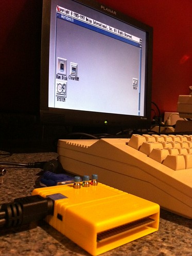
 The Chameleon 64 is a great cartridge. With each release of the firmware, new features are being unlocked. Recently, the Minimig core was ported to the Chameleon 64 which means you can now have a fully emulated Amiga that fits in the palm of your hand.
To play games using a joystick, you need a CDTV infrared (IR) remote. They are still available for purchase here and here but it would take a few weeks for it to arrive.
I wanted to see if it’s possible to convert a standard joystick to wireless IR communications. I know it can be done– I’ve had some experience using Arduino’s to communicate over IR with a vintage LED sign I have. I reverse engineered the original protocol by using the original remote to the sign. That project taught me a lot.
In this case, I don’t have the remote. So I asked on the forum and got a response from the programmer of the Chameleon IR code with all the info I needed (Thanks Peter!).
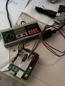
This version uses an original Nintendo NES game pad for the joystick but this could be easily changed to support a standard 9-pin Commodore/Amiga/Atari style joystick. The gamepad is connected to the Arduino and decoded into button presses. It then transmits it via infrared signals to the Chameleon. The code uses the Arduino-IRremote library with additions (included) for the CDTV remote type added.
Download CDTV IR Remote
Category Archives: Retroputing
eBay Oddity: Silver Reed EB-50
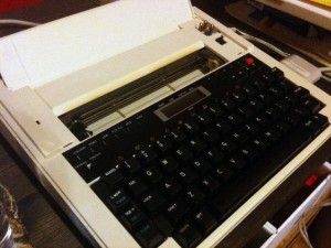 Today I present to you the Silver Reed EB-50. Made in 1985, this thing has a bit of an identity crisis. It’s a printer, a plotter and a typewriter all in one. The reason I got it was because it uses the same tiny ball-point pens that the Commodore 1520 printer/plotter uses. However, this prints on normal 8.5″ wide paper. It’s also very portable, has a lid that covers the keyboard and a flip out handle. It can run on batteries (5 x D cells OMG heavy) or on DC 7.5V power (center negative in case you want to know). For $9.99 it was a bargain curiosity that I couldn’t pass up.
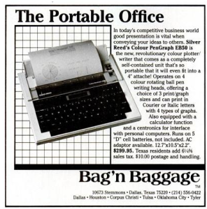 In normal typewriter mode, you press a key and it will “draw” that character in one of 3 sizes, styles or directions in one of 4 colors. You can position the print head anywhere you’d like to print text. In addition, there are function keys to create graphs, right on the typewriter. Pie charts, bar graphs and line graphs are simple– select the type, enter the data points and it prints a graph at the print head position. Pretty clever for something that works sans computer.
Switch it to printer mode and now a computer takes over via the parallel port. This is where things got weird. I found reference to someone that wrote a program to convert HPGL plotter files to ones that printed on this one. This was key since there was no manual and I ran out of internets. But the file was locked up in a “drivers” ad supported nightmare of a website that had me install some bullshit driver manager on Windows to “install” a C code source file. What-fucking-ever. It’s included below in you want it.
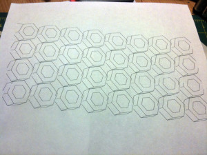 A quick Processing sketch later and I’ve produced some output on it from my Mac using an old PowerPrint serial to parallel adapter via a KeySpan USB to serial adapter. Lots of adaptation, but what do you expect from a nearly 26 year old printer.
# hp2eb50.c
#include <stdio.h>

#define SCAL(x) (((x)+halfscale)/scale)
#define NUMV(x) ((x)=='-' || ((x) <= '9' && (x) >= '0'))
#define SP ('S'<<8)+'P'
#define PU ('P'<<8)+'U'
#define PD ('P'<<8)+'D'
#define PA ('P'<<8)+'A'
#define IW ('I'<<8)+'W'
#define SC ('S'<<8)+'C'
#define LB ('L'<<8)+'B'

FILE *source, *plotter;
short c,i,j,pen,scale,x1,x2,y1,y2,hx,hy,halfscale;
short befehl,ende,rot, colour[] = {0,1,2,3,0,1,2,3};
char param[100], *output;

void upcase(s)
   char *s;
  {
   register char c;
   register int  i=0;

   while ((c = *(s++)) && i<99)
     {
      param[i++] = (c>='a' && c<='z')? c-'a'+'A' : c;
     }
   param[i] = 0;
  }

short get_num()
  {
   register short c,x=0;
   short s;

   if (ende) return(0);
   else
     {
      while(((c = getc(source)) & 0x1ff) <= ' ');
      if (c == '-')
        {
         s=-1;
         c = getc(source);
        }
      else s=1;
      while (c >= '0' && c <= '9')
	{
	 x = x*10+c-'0';
         while(((c = getc(source)) & 0x1ff) <= ' ');
	}
      if (c == ';') ende = -1;
      return(x*s);
     }
  }

void rotate()
  {
   register short h;

   if (rot)
     {
      y2 = y1;
      h = x1; x1 = y1; y1 = -h;
     }
  }

main(argc,argv)
   int argc;
   char *argv[];
  {
   if (argc<2)
     {
      printf("Usage: %s <hpgl-file> [SCALE <scale>] [ROT] [COLOUR <n1..n8>] [TO <output filename>]n",argv[0]);
      exit(0);
     }

   rot = 0;
   output = "par:";
   for (i=2;i<argc;i++)
     {
      upcase(argv[i]);
      if (!strcmp(param,"ROT")) rot=1;
      if (!strcmp(param,"SCALE") && i<argc-1)
	{
	 scale = atol(argv[++i]);
	 if (scale == 0) scale = 1;
	}
      if (!strcmp(param,"TO") && i<argc-1) output = argv[++i];
      if (!strcmp(param,"COLOUR") && i<argc-1)
	{
	 for (i++,j=0;j<8;j++) colour[j]=(argv[i][j]-'0') & 0x03;
	}
     }
   halfscale = scale/2;

   if (!(source = fopen(argv[1],"r")))
     {
      puts("Sorry - Can't open file!");
      exit(0);
     }
   if (!(plotter = fopen(output,"w")))
     {
      puts("Sorry - Can't open output file");
      fclose(source);
      exit(0);
     }

   pen = 0;
   fputc(18,plotter);
   puts(" Command no.:");
   j = 1;
   do
     {
      i = ende = 0;

      do
	{
	 c = getc(source);
	} while (((c < 'A') || (c > 'Z')) && (c != -1));
      befehl = (c==-1)? 0 : (c & 0xff)<<8 | (getc(source) & 0xff);

      printf("2331A23313C %5dn",j++);

      switch(befehl)
        {
         case SP : {
		    x1 = get_num();
		    if (x1)
                      fprintf(plotter,"C%d;n",colour[(x1-1)&7]);
                    break;
		   }
         case PU : {
         	    pen = 0;
		    break;
		   }
         case PD : {
		    pen = 1;
		    break;
		   }
         case PA : {
		    while (!ende)
		      {
		       x1 = SCAL(get_num());
		       if (!ende)
			{
		  	 y1 = SCAL(get_num());
			 rotate();
		         if (pen==1)
                             fprintf(plotter,"D%d,%d;n",x1,y1);
		           else
                             fprintf(plotter,"M%d,%d;n",x1,y1);
			}
		      }
		    break;
		   }
	 case LB : {
		    fputc('P',plotter);
	            while((c = getc(source)) >= 32)
		      putc(c,plotter);
		    putc(13,plotter);
		    putc(10,plotter);
		    break;
		   }
         case SC : {
		    x1 = get_num();
		    if (ende) break;
		    x2 = get_num();
		    y1 = get_num(); y2 = get_num();
		   }
         case IW : {
		    if (befehl==IW)
		      {
		       x1 = get_num(); y1 = get_num();
		       y2 = get_num(); y2 = get_num();
		      }
		    hx = (x2-x1+999)/1000;
		    hy = (y2-y1+999)/1000;
		    hx = (hx>hy)? hx : hy;
		    if (scale<hx)
		      {
		       scale = hx;
		       halfscale = scale/2;
		       printf("New scale: %dn2331A",scale);
		      }
		    rotate();
		    fprintf(plotter,"M%d,%d;nI;n",SCAL(-x1),SCAL(-y2));
		   }
        }
     } while (c!=-1);
   fputc(17,plotter);
   fclose(source);
   fclose(plotter);
   puts("nReady.n");
  }
Print from iPad to ImageWritter II
What if you could print from and iPad to an ImageWriter II? Okay, maybe you don’t want to, but it was an exercise that ultimately proved to be fairly simple.
First, you’ll need a USB to serial adapter and the appropriate cables. I was lucky to have a Keyspan “USA-28X” 2-port adapter with 8-pin DIN jacks, just like the ImageWriter has. I suppose any serial port (9 or 25 pin) would work as long as you had an appropriate cable with 8-pin DIN on the other side. (You may also need to “null modem” the connection this way– not sure).
Next, you’ll need some drivers. Lucky for me, there’s updated drivers for 10.6 available at http://www.linuxfoundation.org/collaborate/workgroups/openprinting/macosx/imagewriter. Download and install the drivers for the ImageWriter II as well as GhostScript (this acts as the RIP to go from PDF to raster images for the printer).
Then you need to configure the printer. By default, the drivers install a print driver for every serial device on you computer. I chose to delete them all and add only one to prevent the clutter. I deleted the extra printers in the Printers Preference Pane. To add the ImageWriter II printer, browse to http://localhost:631/admin which will let you access CUPS on your machine. Go through the add printer procedure, choosing the right serial port, 9600 baud, 8,n1 and hardware flow control (match this to the DIP switches of your printer). Don’t forget to turn on printer sharing and to “share” this new printer!
Finally, you need to download and run AirPrint Activator 2.0 to enable AirPrint on your shared printers.
If all worked, you should see a new printer listed on your iPad (or iPhone/iPod Touch) and relive the sound of the 80’s all over again.
Commodore 1520 Printer Plotter
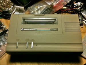 My first computer was a Commodore VIC-20. I got it as a Christmas present from my parents in 1982. I’m pretty sure they picked it up at Montgomery Ward, which was still around at the time. Shortly there after, I got my first printer to go with it. A Commodore 1520 Printer Plotter.
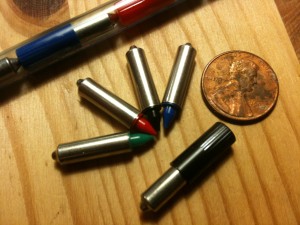 This printer was great. Firstly, it was tiny for a printer. It was smaller than the computer! Everything about it was tiny. It used tiny 4.5″ wide paper that was on a roll. It used tiny ball-point pens (yes, pens!) of four colors that it could selectively choose. I used it well, mostly printing nonsense I’m sure. Time passes and the printer disappears. I think I may have “taken it apart” which for me at that time usually meant destroying it. In any case, the original never followed me.
Fast forward to 2001 when I bought two from eBay. One came with the box and some extra pens (which proved to be the most elusive consumable). But irritatingly, the printer seemed to have fits when it was asked to print something. The motors would make an unpleasant noise and the print head would vibrate in place. The paper advance was also acting up.
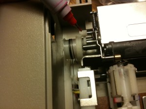 Upon further inspection and some help from the interwebs, I found the culprit. A very tiny gear connects the stepper motor to the rest of the gearing to move both in the X (print head left and right) and Y (paper up and down). These two gears, made of nylon or plastic, have shrunk over time and split, causing the teeth of the gear to get jammed. Commodore sourced the plotter mechanism from ALPS (as did Tandy, Atari and Mattel for their plotters). Likely all plotters using this mechanism are suffering the same fate. Frustrated, I shelved it.
Fast forward to 2009 when I take a course in historical computers, I decided to revisit the printer to see if I can repair it. I found a terrific resource on a Commodore 128 forum from user “airship” he calls The 1520 Plotter Survival Guide written in 2007. It lists sources for the paper, the pens and possible help in fixing the gears.
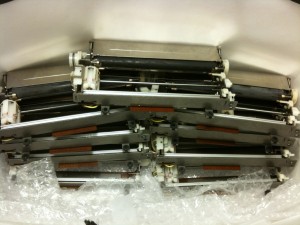 To fix the gear issue, I decide to take the repair route. A company called Electronic Goldmine has the ALPS plotter mechanism (surplus) that Commodore used (at $1.49 ea!). I buy 10, hoping that at least a couple of the gears will be good. All of the gears are split– time has not been good to them. But the good news is the mechanisms make great replacements if the original motors are bad. Plus it gives me 20 gears to try and fix various ways.
To repair the gears, I first remove them from the stepper motor. They’re just pressure fitted so they slide off. I used some super glue to fix the split back together and clamp it together overnight. I then use a 1/16″ drill bit to drill out a tiny amount of the center of the gear. This will relieve the strain and prevent further splitting when the gear is back on the motor shaft. Next, I dry test the gear on the motor and see if it works. If it does, I use super glue to attach the gear to the shaft.
The result:
It works! I keyed in a demo program from the manual and produced this:
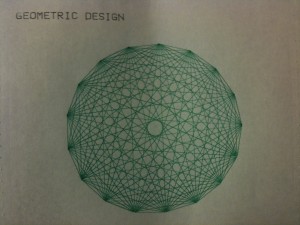
Coming up in another post I’ll show you what it looks like when it plots text (with slow motion video).
Microsoft BASIC Timeline + Easter Eggs
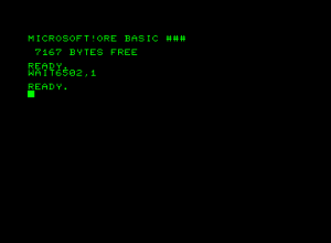 This is a fascinating history of Microsoft BASIC, that starts from it’s origins on the Altair 8800 through to the Commodore 128. Gates himself inserted several “easter eggs” in the code for BASIC in case it was ever lifted by another company for use in another machine– he’d have the proof.
Link.
Talking to an old PTZ camera
 I recently obtained an old Polycom PTZ-1 camera. This camera went to an old video conferencing system, long past it’s usefulness in today’s era of instant desktop video conferencing ala Skype. The camera was inside a large plastic housing to keep it secure– I removed it from the housing to get a closer look.
I know most cameras are controlled via RS-232 so I searched around and found a site that listed the control codes necessary to talk with this camera. I also found how to build the cable to go from a serial DB-9 to a mini-din 8 here. That’s where the Arduino comes in.
Previously, I figured out how to interface an NES joy-pad to the Arduino (even purchasing the proper female jacks so I wouldn’t need to cut the original cables). So I thought about marrying the camera with the controller. Behold, the the Picture PTZ-1 being controlled by the Arduino via an NES joypad.
The first problem I encountered was that the PTel PTZ-1 liked to talk serial using ODD parity. Yikes, I didn’t think the Arduino could do that. Well, it can actually. I found a forum posting that listed an extension to the serial protocol of the Arduino.
Although the Arduino has on board serial, it needs help to speak RS-232 serial (because of voltage differences). That’s where the MAX232 chip comes in and it’s cast of supporting capacitors.
Below is the Arduino sketch that I’m using. The code will pan and tilt the camera using the plus-pad. The A and B buttons control zoom in and out. Select and Start are for presets. The camera has 8 hardware presets. Press select the number of times equal to the preset you want and press start. To set a preset, press select the number of times equal to the preset, holding on the last preset and press start.
#include <SerialExtension.h>
# NES Controller Pin Setup
int latch = 8; // set the latch pin
int clock = 9; // set the clock pin
int datin = 10; // set the data in pin
# A Status LED To Light When Receiving input from NES
int ledpin = 13; // set the led status pin
# Zero Counters
int selects = 0;
int starts = 0;
unsigned char report[6];
unsigned char prev_report[6];
void setup() {
// Setup NES controller
pinMode(latch, OUTPUT);
pinMode(clock, OUTPUT);
pinMode(datin, INPUT);
pinMode(ledpin, OUTPUT);
digitalWrite(latch, HIGH);
digitalWrite(clock, HIGH);
Serial.begin(9600);
SetSerial(9600,’O’, 8, 1);
delay(500);
init_camera();
report[0]=0x80;
report[1]=0x80;
report[2] = report[3] = report[4] = report[5] = 0;
prev_report[0]=0x80;
prev_report[1]=0x80;
prev_report[2] = prev_report[3] = prev_report[4] = prev_report[5] = 0;
}
void loop () {
NEScontrollerRead();
// Tilt up begin
if ((report[1] == 0) && (prev_report[1] == 0x80)) { motion_begin(‘t’, ‘u’); }
// Tilt up stop
if ((report[1] == 0x80) && (prev_report[1] == 0)) { motion_stop(‘t’, ‘u’); }
// Tilt up cont
if ((report[1] == 0) && (prev_report[1] == 0)) { motion_cont(‘t’, ‘u’); }
// Tilt down begin
if ((report[1] == 0xFF) && (prev_report[1] == 0x80)) { motion_begin(‘t’, ‘d’); }
// Tilt down stop
if ((report[1] == 0x80) && (prev_report[1] == 0xFF)) { motion_stop(‘t’, ‘d’); }
// Titlt down cont
if ((report[1] == 0xFF) && (prev_report[1] == 0xFF)) { motion_cont(‘t’, ‘d’); }
// Pan left begin
if ((report[0] == 0) && (prev_report[0] == 0x80)) { motion_begin(‘p’, ‘l’); }
// Pan left stop
if ((report[0] == 0x80) && (prev_report[0] == 0)) { motion_stop(‘p’, ‘l’); }
// Pan left cont
if ((report[0] == 0) && (prev_report[0] == 0)) { motion_cont(‘p’, ‘l’); }
// Pan right begin
if ((report[0] == 0xFF) && (prev_report[0] == 0x80)) { motion_begin(‘p’, ‘r’); }
// Pan right stop
if ((report[0] == 0x80) && (prev_report[0] == 0xFF)) { motion_stop(‘p’, ‘r’); }
// Pan right cont
if ((report[0] == 0xFF) && (prev_report[0] == 0xFF)) { motion_cont(‘p’, ‘r’); }
// Zoom in begin
if ((report[2] == 1) && (prev_report[2] == 0)) { motion_begin(‘z’, ‘i’); }
// Zoom in stop
if ((report[2] == 0) && (prev_report[2] == 1)) { motion_stop(‘z’, ‘i’); }
// Zoom in cont
if ((report[2] == 1) && (prev_report[2] == 1)) { motion_cont(‘z’, ‘i’); }
// Zoom out begin
if ((report[3] == 1) && (prev_report[3] == 0)) { motion_begin(‘z’, ‘o’); }
// Zoom out stop
if ((report[3] == 0) && (prev_report[3] == 1)) { motion_stop(‘z’, ‘o’); }
// Zoom out cont
if ((report[3] == 1) && (prev_report[3] == 1)) { motion_cont(‘z’, ‘o’); }
// Select button function
if ((report[4] == 1) && (prev_report[4] == 0)) {
selects++;
if (selects > 8) { selects = 0; }
}
// Select and Start functions
// Goto preset
// Press “Select” times to equal the number of the preset
// then press “Start” to go to that preset.
if ((report[5] == 1) && (prev_report[5] == 0) && (report[4] == 0)) {
if (selects > 0) {
command_begin();
Serial.print(“g0”);
selects–;
Serial.print(selects);
Serial.print(“n”);
command_end();
selects = 0;
}
}
// Store preset
// Press “Select” times MINUS 1 equal to the numer of the preset to SET
// Press and HOLD “Select” on the last number and press “Start” to set the preset
if ((report[4] == 1) && (report[5] == 1) && (prev_report[5] == 0)) {
if (selects > 0) {
command_begin();
Serial.print(“s00”);
selects–;
Serial.print(selects);
command_end();
selects = 0;
}
}
prev_report[0] = report[0];
prev_report[1] = report[1];
prev_report[2] = report[2];
prev_report[3] = report[3];
prev_report[4] = report[4];
prev_report[5] = report[5];
delay(100);
}
void NEScontrollerRead() {
int x = 0x80, y = 0x80; // 0x80 = 128 = axis centered (nothing pressed)
int a, b, select, start, led = 0;
report[0] = report[1] = report[2] = report[3] = report[4] = report[5] = 0;
unsigned char tmp = 0;
digitalWrite(latch, LOW);
digitalWrite(clock, LOW);
digitalWrite(latch, HIGH);
delayMicroseconds(2);
digitalWrite(latch, LOW);
// button A
a = !digitalRead(datin);
NESCycleClock();
// button B
b = !digitalRead(datin);
NESCycleClock();
// button Select
select = !digitalRead(datin);
NESCycleClock();
// button Start
start = !digitalRead(datin);
NESCycleClock();
// button Up
if (!digitalRead(datin)) { y = 0; led = 1;}
NESCycleClock();
// button Down
if (!digitalRead(datin)) { y = 0xff; led = 1; }
NESCycleClock();
// button Left
if (!digitalRead(datin)) { x = 0; led = 1; }
NESCycleClock();
// button Right
if (!digitalRead(datin)) { x = 0xff; led = 1; }
NESCycleClock();
report[0] = x;
report[1] = y;
report[2] = a;
report[3] = b;
report[4] = select;
report[5] = start;
//report[2] = (a << 0) + (b << 1) + (select << 2) + (start << 3);
if (a || b || select || start || led) { digitalWrite(ledpin, 1); }
else { digitalWrite(ledpin, 0); }
}
void NESCycleClock() {
delayMicroseconds(4);
digitalWrite(clock, LOW);
digitalWrite(clock, HIGH);
delayMicroseconds(2);
}
void command_begin() {
Serial.print(0x02, BYTE);
Serial.print(“ck”);
}
void command_end() {
Serial.print(0x04, BYTE);
}
void init_camera() {
command_begin();
Serial.print(“k”);
command_end();
command_begin();
Serial.print(“i0n”);
command_end();
// Wait for an ACK from camera
while(Serial.read() != 0x04) {}
command_begin();
Serial.print(“d0”);
Serial.print(0xF2, BYTE);
command_end();
delay(100);
// Wait for an ACK from camera
while(Serial.read() != 0x04) {}
command_begin();
Serial.print(“z0m”);
command_end();
// Wait for an ACK from camera
while(Serial.read() != 0x04) {}
}
void motion_begin(char axis, char dir) {
command_begin();
Serial.print(“r0k”);
Serial.print(axis, BYTE);
Serial.print(dir, BYTE);
if (dir == ‘u’) { Serial.print(“099”); }
if (dir == ‘d’) { Serial.print(“097”); }
if (dir == ‘l’) { Serial.print(“100”); }
if (dir == ‘r’) { Serial.print(“101”); }
command_end();
}
void motion_cont(char axis, char dir) {
command_begin();
Serial.print(“c0k”);
Serial.print(axis, BYTE);
Serial.print(dir, BYTE);
command_end();
}
void motion_stop(char axis, char dir) {
command_begin();
Serial.print(“p0k”);
Serial.print(axis, BYTE);
Serial.print(dir, BYTE);
command_end();
}
For the love of 8 bits.
Some local artists who know who to rock it with only 8 bits.
/* Wait for VBLANK */
Alex Mauer
no-carrier
Floggidog
8GB
And a live event coming up..