If you have a Commodore 64, chances are you’ll eventually need to connect a modem or other serial device to it. You’ll find that’s not quite that easy since the C64 doesn’t have a standard RS-232 serial port. What it does have is called the “user port” and it can do serial over this port but it needs to be changed from TTL levels (0 to +5v) to RS-232 levels (-15v to +15v).
If you’ve ever attempted to purchase a VIC-1011a terminal type, SwiftLink or Turbo232 from eBay you’ll quickly find out that the price gets out of hand. Expect to pay upwards of $100 or more for these adapters.
Luckily, there’s an inexpensive way to get a RS-232 port on your C64 and it’ll cost you less than $15. Ready?
You’ll need these parts for the project.
- DFRobot RS232-TTL Module from Jameco.com for $10
- User port edge connector from eBay for $1.75
- Null modem adapter
- Connecting wire
- Soldering iron
Connect the RS232-TTL module directly to the C64 user port edge connector using the table below.
| RS232-TTL Module | C64 User Port |
|---|---|
| GND | A & N |
| TXD | M |
| RXD | B & C |
| VCC | 2 |
Update! Alwyz from 1200baud suggested that connecting VCC isn’t necessary and potentially dangerous. I’ve had zero problems with mine as listed here. I’m providing this warning so you can make your own decision!
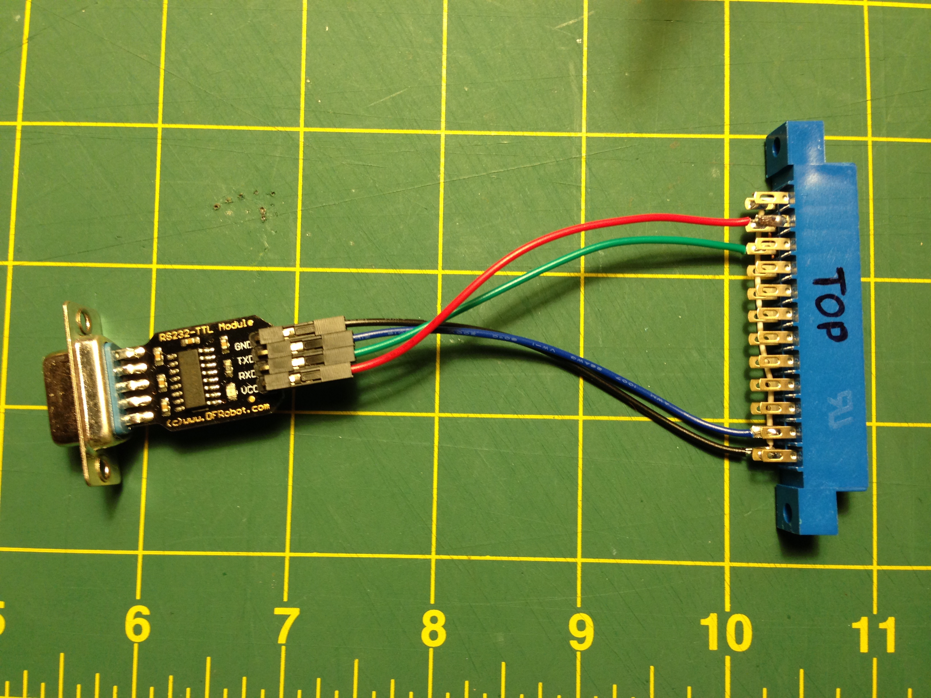
Observe which side of the user port connector is the top (it’s the one with numbers– letters are on the bottom). It’s helpful to write on it with marker. For wire I used female jumper wire that I cut one end off. For GND and RXD you’ll need to jumper two of the pins together on the user port connector. I used a small bit of CAT5 solid core wire.
Once you’ve got it connected, add the null modem adapter and connect your modem. You may need to also use a gender changer and/or a 9 pin to 25 pin adapter depending on your modem.
Fire up CCGMS, Novaterm or Striketerm, set the baud rate to 2400, set the port to the user port and give it a few “AT” commands. You should see “OK” being returned. If it doesn’t, make sure you have a null modem adapter (test it on another machine to confirm) and double check your connections.
As with any tutorial you find online, be responsible and double check my work and your work before proceeding.
dasistdaniel
March 12, 2014 at 4:48pmI don’t have a C64 now to test it myself but there is a serial bluetooth module i use on an Arduino. It’s called HC-06 (Datasheet) and maybee you could use it to get a wireless Bluetooth Connection to the C64.
paulrickards
March 16, 2014 at 1:48pm@dasistdaniel Very interesting, that would be a great project to try. I think it would be a great project to create a cartridge that accepted a Lantronix XPort (Ethernet) or Matchport (WiFi) for a C64. Cheers!
RS-232 – C64 | Commodore Is Awesome
March 17, 2014 at 2:28am[…] module you can make a real RS-232 port with the necessary -15 Volt and +15 Volt levels.Website: http://paulrickards.com Category: Link […]
Michael
April 25, 2014 at 9:11pmI tried it out, now both of my C64 is dead because of this.. I did exactly like you wrote it.
paulrickards
April 29, 2014 at 10:59pmHi Michael, Sorry to hear that. A couple of folks on Twitter were able to successfully build the interface. I’m not sure how it could “kill” a C64 unless the RFRobot adapter is faulty (even that is a stretch). Have you had luck in troubleshooting them?
Nick
December 17, 2016 at 8:53amI did the same thing. It’s easy to put the user port connector upside down. All you need to do is open up your C64 and replace the fuse. Replace with a 1 1/2A, 1/4″x 1 1/4″ fuse. Hardware stores sell these for only a few bucks.
Nick
June 28, 2014 at 2:15pmHey this is Alwyz from 1200baud . I just wanted to point out the VCC to pin 2 is unnecessary and a bad idea. Added voltage that doesn’t need to be present shouldn’t be there. 5v is already running on the TxD line as it is. Damage could occur as a result of VCC being connected.
paulrickards
June 28, 2014 at 3:42pmHello! I’m not sure I understand 100% as TxD would be a signal line and not a constant source of power? I’ve made a couple of these and tested them as have a couple of folks on Twitter with no ill effects. In any case, more information the better! Thanks for the info!
garion
July 26, 2014 at 10:03pmI tried it without the VCC, and I was able to receive data on the c64, but not send it. Once I hooked up the VCC, I was able to send. So in my case, VCC was needed.
paulrickards
July 26, 2014 at 11:12pmHi Garion, Thanks for the report! Glad it’s working for you.
Rob
November 18, 2018 at 2:23amI had this same idea to use a cheap TTL-RS232 module to adapt the user port to RS232 on my C64, so I was happy to see this page as a sanity check. So I put one together with stuff from my junk bin toady and it looked like everything was cool–had Novaterm running and I could see that everything on the C64/adapter side was working on an oscilloscope (I could see characters being sent when I typed them). I was working pretty methodically using the scope to make sure everything was safe. However, when I then attached the TTL converter to a USB-Serial adapter on my PC, the C64’s CIA at U2 died. Since everything initially looked good on the scope I don’t know what happened, but maybe there is a lesson in that not all of these RS232/TTL adapters are the same. Being super cheap I used a $0.99 TTL converter and an RS232-USB adapter that was maybe $3.00 (both from China on eBay). It could be that different revs of the C64 have different risks–this was a 250407 board lacking the protection diodes CR100-105 that are present in other designs. Might also be that there was some funny ground loop that killed it since I also had a Raspi hat for a Pi1541 emulator connected at the same time, and the IEC serial is driven by the same chip. Oh well, now I’m waiting for a replacement CIA…
Darl3ne Alders0n
August 17, 2020 at 5:22pmThe first question should be: Will it be connected to a RS-232 module (MAX232, MAX3232) or USB module (FTDI et.al.)?
1. RS-232 modules are not bus powered, therefore they require a 5V supply from the computer. Some modules optionally run on 3.3 or 5V and match their I/O levels to their supply voltage.
2. USB modules/cables are powered by the bus, they have a voltage output and connecting them to 5V at the computer is dangerous. (Be careful: There are 3.3V variants, too! Plug into USB and measure the Vcc pin.)
3. Some USB modules have multiple voltage support and come with a voltage *input* that is used to match their I/O levels. This input should be connected to 5V at the computer.
Todd
January 11, 2016 at 10:28pmHi there, thanks for this article. Worked like a champ for me. Vcc is required, that’s what powers the converter chip (MAX3232 in my case). Otherwise, the chip is only powered intermittently when data is transmitted. I had similar results to Garion above where one direction worked but the other didn’t. The one direction that worked had random data corruption. All of this was cured by connecting the Vcc line thus properly powering the RS232 converter chip.
ToGeo.com » Blog Archive » Retro Challenge 2015 – Update #2 – Serial Comm Established
January 17, 2016 at 8:33pm[…] to an awesome blog post over at Biosrhythm, I now have RS232 serial communication to/from the Commodore 64. I built what is essentially the […]
MMS
December 25, 2016 at 10:58amHi,
I started to work on a similar project 2 years ago with a friend on Commodore plus/4, and seems after the max232 IC based self made prototypes we arrived to the same” ready from the shelves” solution.
I have a comment, though i can be wrong, as the plus/4 has different user port layout, but for an other project I tried to make a pin conversion table.
I think, that maybe the TXD (transmit) line of the converter module linkage to the M pin could be connected to the B that is expecting an input to set CIA2 flag. So i think the input and output lines are swapped. Sorry if I was wrong. (Even this cannot kill the machine as described. But the user port TOP should be clearly marked)
Eric
January 8, 2017 at 4:12amWulfden P3 adapter worked perfectly, no issues with VCC, (you need to power the adapter!). Look at the photo, mark the top of the connector! Had a ton of fun today on telnet bbs with my C64! Thanks much!
Thilo
August 9, 2017 at 3:58amPaul,
thank you for this post!
This will be worth a try for me.
One question for clarification: Did you bridge pins B and C?
That’s not very clear from the picture.
Thanks
Thilo
paulrickards
August 9, 2017 at 8:50pmYes, pins B and C are bridged on the C64 user port. Do make sure that you label the top of your user port plug with “TOP” to prevent from accidentally plugging it in upside-down! There’s 9VAC present on some of the other pins. Good luck!
Thilo
August 24, 2017 at 10:46amThanks for the input, Paul!
Yes, that’s pretty important. For the cassette port, I tend to write the functions on top. Shows me the top, of course, and also where to connect my clips to.
I might try and glue in a proper key for the user port connector.
SpeedStar
September 6, 2017 at 5:05pmI built this today, and managed NOT to fry my C64 (thank you all for the warning, the connector is marked ‘TOP’)
However, I cannot seem to get anything out of it. if I type ‘AT’ in CCGMS i get nothing whatsoever. I DO have a nice light on my adapter, but thats it.
I am totally stumped, any help would be great. Im certain all my connections are correct.
paulrickards
September 6, 2017 at 5:28pmYou can try plugging in a jumper between pins 2 and 3 of the DB-9 connector on the RS-232 side. This is a quick “loopback” that will echo characters back to your screen as you type them on the C64 terminal.
If that works, you may have to use a null modem connector at the RS-232 side (it swaps RX/TX pins).
Good luck!
Speedstar
September 7, 2017 at 3:40pmThat worked, thank you!
I am trying to connect the c64 to my raspberry pi and use tcpser as a modem. I had one of those pretty useless usb to serial cables plugged in, and i think thats what the issue is. I can connect another ttl module to the pi but ill have to wait for delivery from ebay…
I am really pleased that i can prove my construction skills were at least passable.
Thank you for your help. Now my c64 has an rs232 port maybe ill scour ebay for a US Robotics…
🙂
Blake
November 15, 2017 at 2:46pmCould this be used with a 25-9 pin adapter to use the wifi232?
Dan Price
May 18, 2018 at 4:08amI’m thinking of making one of these in a little case (actually the shroud of a parallel port connector). Since I’m hanging stuff off the user port, I was thinking of putting a reset switch into the case as well – just a push button wired across pins 1 & 3 (GND & /RESET). Would this be a bad idea without adding diodes etc. since the TTL converter is also connected to ground in the user port?
Barry Chambers
July 19, 2018 at 6:45pmIf I have a similar adapter that has also has RTS and CTS. Can I hook them up as RTS -> Pin D and CTS -> Pin K? Will that work?
James
October 8, 2018 at 4:47pmHi I’m confused what the null modem adapter is for? If it just connects rx to tx and makes it the opposite why not just connect rx to tx and vice versa instead thus cutting out the need for the null modem adapter?